


- Lesson 1: Software Downloading / Installing & Interface
- Lesson 2: Basic Code
- Lesson 3: Sensors: Potentiometers
- Lesson 4: Sensor: Infrared Distance
- Lesson 5: Actuator: Servo Motor
- Lesson 6: Sensor: Force, Bend, Stretch
- Lesson 7: Sensor: Accelerometer, Gyro, IMU
- Lesson 8: Shield: Wheatstone Bridge & LCD
- Lesson 9: Programming Arduino Platforms Using a Different IDE
- Computer / Laptop or Netbook
- Arduino Microcontroller
- USB to Serial Adapter (if your microcontroller does not have a USB port)
- Appropriate USB cable (Arduino boards draw power from the USB port – no batteries yet)
- Analog accelerometer, gyroscope, and/or IMU
- Connectors (between the IMU and the Arduino)
Accelerometers, gyroscopes, and IMUs are incredibly useful little sensors that are being integrated more and more into the electronic devices around us. These sensors are used in cell phones, and gaming consoles such as the Wii wireless remote control, toys, self-balancing robots, motion capture suits, and more. Accelerometers are used mainly to measure acceleration and tilt, gyroscopes are used to measure angular velocity and orientation, and IMUs (which combine both accelerometers and gyroscopes) are used to give a complete understanding of a device's acceleration, speed, position, orientation, and more.
When choosing an accelerometer, gyroscope, or IMU, it is also important to consider the type of output; depending on the type of sensor, readings can be output as:
- Serial data (Tx pin)
- I2C (SDA, SCL)
- Analog
- TTL
- others...
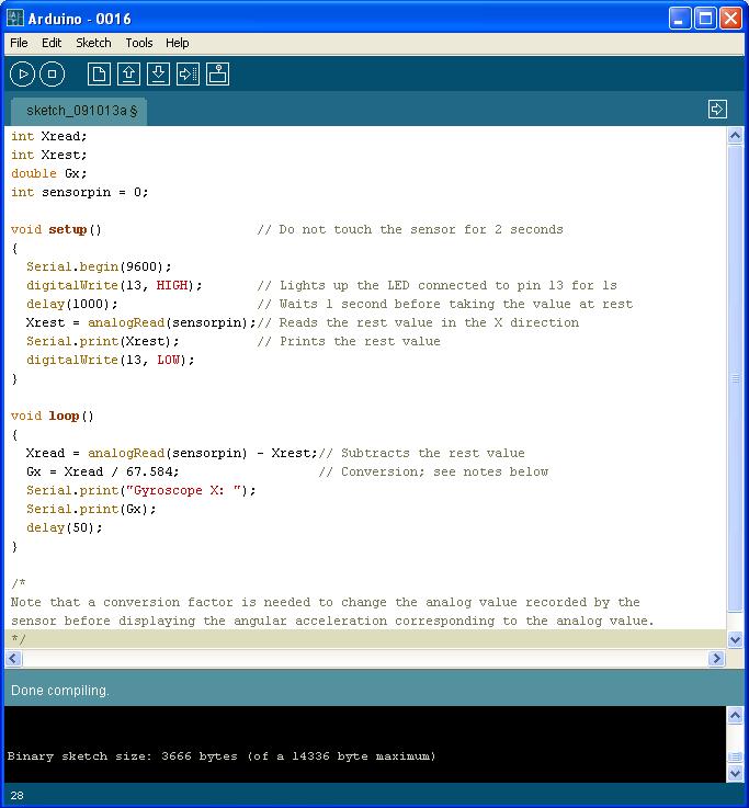
In this tutorial, we're only going to cover analog output. The code shown below includes the output for a single-axis sensor and factors in the best value.
Accelerometers measure acceleration in one to three linear axes (x, y, z). A single-axis accelerometer can measure acceleration in whichever direction it is pointed. This may be good for a rocket, an impact, a train, or other scenarios where the device really moves in one basic direction. Knowing the acceleration and time, you can use mathematics to find the distance traveled by the object. There are fewer and fewer single and double-axis accelerometers on the market because a triple-axis accelerometer can do so much more. Thanks to low manufacturing cost the three axes accelerometers are not much more expensive than single or double.
Acceleration due to gravity is a constant and is in fact measurable using an accelerometer. When placed parallel to the ground, acceleration due to gravity would only be "felt" by one axis. However, when tilted, this acceleration would appear as components of two (or three) axes. You can get an idea of how to use an accelerometer to measure tilt here.
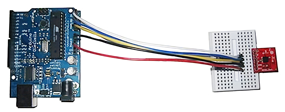
Connect the accelerometer to the Arduino; each output pin goes to one of the analog pins on the Arduino, and the Vin pin goes to the 5V pin on the Arduino (read the user guide to ensure the Vin pin is 5V as opposed to 3.3V), and connect the GND pin to the GND pin on the Arduino. Note that there is no need for additional electronics! Next, open the sample sketch File -> Examples -> Sensors -> ADXL3xx. Upload to the Arduino and see the values change.
In order to choose the right accelerometer, consider the maximum linear acceleration the sensor will be subjected to. If you are planning to add an accelerometer to a small mobile robot, you will likely use a 2g accelerometer (even that is likely overkill), whereas if you are attaching it to a rocket, a 16g accelerometer is likely a better choice. When connected to a 10-bit ADC, the 2g accelerometer will have an accuracy of 2 / 1024 = 0.002g, and the 16g accelerometer will have an accuracy of 16 / 1024 = 0.0156. Therefore if you only need a range of 2g, but purchase a 16g accelerometer, you will only have about 128 possible readings, instead of the full 1024. Conversely, if you choose a 2g accelerometer when you really needed a 16g, you will get a lot of "maximum (1024) "readings since the acceleration is "off the scale".
Gyroscopes measure angular velocity in α, β, γ (see image below). Gyroscopes can be used to help with stabilization as well as changes in direction and orientation. Unlike accelerometers, gyroscopes do not have a fixed reference, and only measure changes. To choose the right gyroscope for your needs, consider the maximum angular rate of change (degrees per second) your product will be subjected to. A remote control will likely rotate at less than 1 rotation per second (360 degrees per second), while a rocket tumbling out of the sky may be rotating at 1500 degrees per second. When connected to the same microcontroller (10-bit for example), the 360 degree/s gyro will have an accuracy of 360 / 1024 = 0.35 deg/s, whereas the 1500 deg/s gyro will have an accuracy of 1500 / 1024 = 1.46 deg/s. Therefore if you chose a 1500 deg/s gyro when you only needed a 360 deg/s gyro, you will only get about 245 readings as opposed to 1024.

Source: Wikipedia
An IMU (Inertial Measurement Unit) usually consists of an accelerometer and gyroscope and is used to measure an object's orientation, velocity, etc. Often additional sensors (magnetic, temperature) are included to improve accuracy. The number of "degrees of freedom" indicates the number of different axes measured by the chip. For example, combining a three-axis accelerometer with a two-axis gyroscope would be considered a 3+2 = 5 DoF IMU.
When using accelerometers, gyroscopes, or inertial measurement units (IMUs) to obtain positions in space, it is important to note that there are several additional factors that will affect the readings, the main obstacle being the sampling rate. Microcontrollers require a certain amount of time to read values being provided to them by the sensor, and because of this, the values between these readings are lost. There are several mathematical methods (a Kalman filter being a popular choice) that attempt to compensate for this. A second source of error is that readings are often affected by fluctuations in temperature. Most datasheets associated with micro-electro-mechanical systems (MEMS) attempt to describe how temperature affects the output.
Want to learn more? Start with the material put out for free by Analog Devices, which makes many MEMS accelerometers, gyroscopes, and other sensors.