


- Lesson 1: Software Downloading / Installing & Interface
- Lesson 2: Basic Code
- Lesson 3: Sensors: Potentiometers
- Lesson 4: Sensor: Infrared Distance
- Lesson 5: Actuator: Servo Motor
- Lesson 6: Sensor: Force, Bend, Stretch
- Lesson 7: Sensor: Accelerometer, Gyro, IMU
- Lesson 8: Shield: Wheatstone Bridge & LCD
- Lesson 9: Programming Arduino Platforms Using a Different IDE
- Computer / Laptop or Netbook
- Arduino Microcontroller
- USB to Serial Adapter (if your microcontroller does not have a USB port)
- Appropriate USB cable (Arduino boards draw power from the USB port – no batteries yet)
- Standard servo motor (current consumption <50mA)
- Pin headers/cables
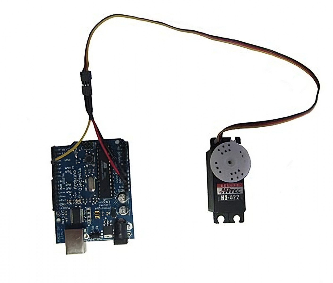
Controlling a servo motor directly from the Arduino is quite easy. However, a servo motor may require significantly more current than the Arduino can provide. The following example uses a standard-sized servo (without any load) powered directly from the Arduino via USB. When powering the servo directly from the Arduino board:
- Connect the black wire from the servo to the GND pin on the Arduino
- Connect the red wire from the servo to the +5V pin on the Arduino
- Connect the yellow or white wire from the servo to a digital pin on the Arduino
Alternatively, you can plug the servo's wire into three adjacent pins, and set the pin connected to the red lead to "HIGH" and the pin connected to the black lead to "LOW". If you want to use a more powerful servo, or if you want to connect it to a separate power supply, you would connect the battery/power supply's red (5V) and black (GND) wires to the servo's red and black wires, and connect the signal wire to the Arduino. Note that you also need to connect the batter's GND line to the Arduino's GND pins ("common ground").
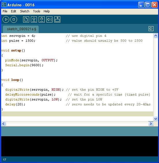
pinMode(pin number, OUTPUT);
This sets a pin number as dedicated input or output. In this case, we called the pin “servopin” and assigned it a value of 4. The term “pulse” is in black as it is not a reserved word and can be changed by the user. It is best to use descriptive variables when coding to understand what each does, or the information it will contain. Servos operate by sending a timed +5V pulse (usually between 500us and 2500us) to the onboard electronics, which is repeated every ~20ms. This pulse corresponds to a servo position, usually from 0 to 180 degrees.
- 5V for 500 microseconds = 0.5 milliseconds and corresponds to 0 degrees
- 5V for 1500 microseconds = 1.5 milliseconds and corresponds to 90 degrees
- 5V for 2500 microseconds = 2.5 milliseconds and corresponds to 180 degrees
- The relationship is linear, so use mathematics to determine the pulse which corresponds to a given angle. Note that if you send a signal that is greater or lower than the servo can accept (for example, Firgelli linear actuators accept 1 to 2 ms), you might damage the actuator.
Another option for controlling servos is to use the Arduino "servo library" (previously separate from the basic Arduino software, it is now included with V1.0). The servo library manages much of the overhead and includes new, custom commands. If you want to control multiple servo motors, you should use a servo motor controller and a separate power supply between 4.8V to 6V.