- Lesson 1: Software Downloading / Installing & Interface
- Lesson 2: Basic Code
- Lesson 3: Sensors: Potentiometers
- Lesson 4: Sensor: Infrared Distance
- Lesson 5: Actuator: Servo Motor
- Lesson 6: Sensor: Force, Bend, Stretch
- Lesson 7: Sensor: Accelerometer, Gyro, IMU
- Lesson 8: Shield: Wheatstone Bridge & LCD
- Lesson 9: Programming Arduino Platforms Using a Different IDE
- Computer / Laptop or Netbook
- Arduino Microcontroller
- USB to Serial Adapter (if your microcontroller does not have a USB port)
- Appropriate USB cable (Arduino boards draw power from the USB port – no batteries yet)
- IR Distance sensor (preferably Sharp) and corresponding cable
- Push button and corresponding cables to connect to Arduino
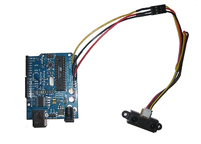
Infrared distance sensors are useful for measuring distances without actually touching a surface. The three wires protruding from a distance sensor represent +5V (in most cases), GND (Ground), and signal. These are almost always color coded with black as ground, red as +V, and white or yellow as the signal. If your infrared distance sensor did not come with any wires, you will either need to find the appropriate connector, or solder wires directly to the leads (ensure the pins and solder do not contact one another) so you can attach wires.
- Connect the red wire to +5V on the Arduino
- Connect the black wire to GND on the Arduino
- Connect the yellow wire to an analog pin on the Arduino (in this case we chose A2)
Since the sensor is connected to the analog input of the Arduino, the code is identical to that of the potentiometer:
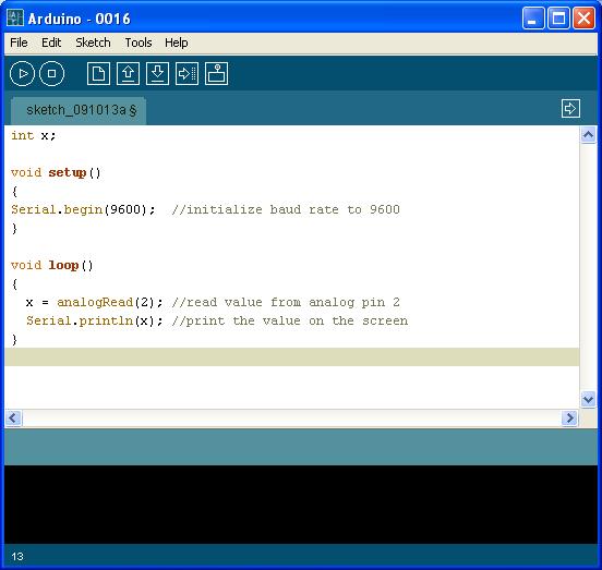
Upload this program to the board and change it to the Serial Monitor. As you move the front of the distance sensor closer to and away from a solid object or wall, the values should change between 0 to 1023. You can now read values and use them within your code. Check the range for your sensor (not all sensors can read from zero cm); note that some sensors have a minimum distance - although it is always listed in the specifications, try to find it by experimentation. To convert the values to actual distances (in cm or inches), consult the user guide of the sensor.
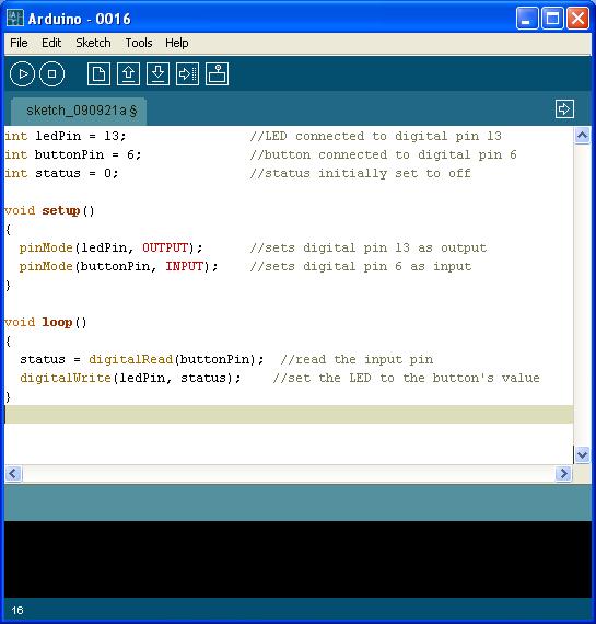
Connecting toggle switches, push buttons, and momentary contact switches to the Arduino is straightforward. A push button is a simple device that completes a circuit. One end of the button is connected to the source, usually, a low voltage (5V on the Arduino is ideal), and the other is connected to the digital pin. When the switch is flipped, pressed, or toggled, the circuit is either opened or closed. The digital pin simply returns if there is 5V or 0V. The code associated with this is:
digitalRead(pin);
In the following simple program, a push button is used to turn on the LED connected to pin 13. The line
digitalWrite(ledPin, status);
turns the ledPin (in this case assigned to digital pin 13) HIGH (1) or LOW (0) depending on the status variable. We initially set the status to low (0).