


- Lesson 1: Software Downloading / Installing & Interface
- Lesson 2: Basic Code
- Lesson 3: Sensors: Potentiometers
- Lesson 4: Sensor: Infrared Distance
- Lesson 5: Actuator: Servo Motor
- Lesson 6: Sensor: Force, Bend, Stretch
- Lesson 7: Sensor: Accelerometer, Gyro, IMU
- Lesson 8: Shield: Wheatstone Bridge & LCD
- Lesson 9: Programming Arduino Platforms Using a Different IDE
- Computer / Laptop or Netbook
- Arduino Microcontroller
- USB to Serial Adapter (if your microcontroller does not have a USB port)
- Appropriate USB cable (Arduino boards draw power from the USB port – no batteries yet)
- Standard servo motor (current consumption <50mA)
- Pin headers/cables
- Bend /stretch sensor and/ or Force sensor
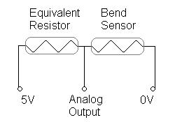
Force “sensors” are actually “force sensing resistors” (FSRs). Similarly, bend “sensors” are actually products whose resistance changes with flexing. These can all be categorized as “variable resistors”. To interface a product whose resistance changes with a microcontroller, you need a voltage divider circuit. This “circuit” is nothing complex – aside from wires, the only part you are missing is a resistor.
To create the circuit, add the variable resistor in series with a similar (standard) resistor of roughly the same resistance (in ohms). Connect a wire between the two - this wire goes to the analog input of the board. There should only be two wires left - one end of the standard resistor, and one end from the variable resistor - these ends are connected to +5V and GND respectively. You can now use it as a regular sensor with analog output.
If you want a pre-made circuit, consider the Phidgets voltage divider:
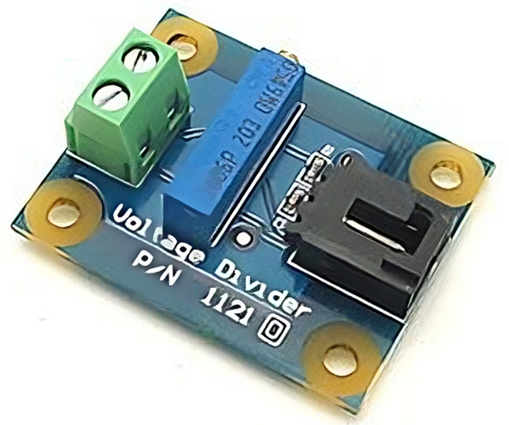
The output of this “mini-circuit” is a signal between 0 to 5V (this is referred to as an analog signal), which is connected to an analog pin of the microcontroller. The microcontroller's onboard analog-to-digital converter (ADC) interprets this voltage and assigns it a number that you can use in your code. For 10-bit ADC (210), you will get a number between 0 and 1024 representing 0V to 5V. You would need an equation in your code to use this number to send the appropriate signal to a motor controller. As you might have suspected, the code is now identical to that used to get an analog input.
To get a sample code, open the Arduino software and go to File -> Examples -> Analog -> AnalogInOutSerial
The video above shows a bend sensor connected to an Arduino, and the Arduino is connected to a small servo motor. The analog value associated with the flex sensor is read by the Arduino, and that value is converted to a rough position. You would merge the Analog example code with the servo code, and add a single line to convert the 0 to 1024 value to 0 to 180 degrees. It is easy to see how, with many of these sensors, you can create a data glove that controls a robotic hand.