


- Lesson 1 – Getting Started
- Lesson 2 - Choosing a Robotic Platform
- Lesson 3 - Making Sense of Actuators
- Lesson 4 - Understanding Microcontrollers
- Lesson 5 - Choosing a Motor Controller
- Lesson 6 – Controlling your Robot
- Lesson 7 - Using Sensors
- Lesson 8 - Getting the Right Tools
- Lesson 9 - Assembling a Robot
- Lesson 10 - Programming a Robot
Now that you have chosen all the basic building blocks used to make a robot, the next step is to design and build a structure or frame which keeps them all together and gives your robot a distinct look and shape.
There is no “ideal” way to create a frame since there is almost always a trade-off to be made; You may want a lightweight frame but it may need to use expensive materials or end up too fragile. You may want a robust or large chassis but realize it will be expensive, heavy, or hard to produce. Your “ideal” frame may be complex and take too much time to design and create when a simple frame may have been just as good. There is also rarely ever an “ideal” shape, but some designs can certainly look more elegant in their simplicity, while others can attract attention because of their complexity.
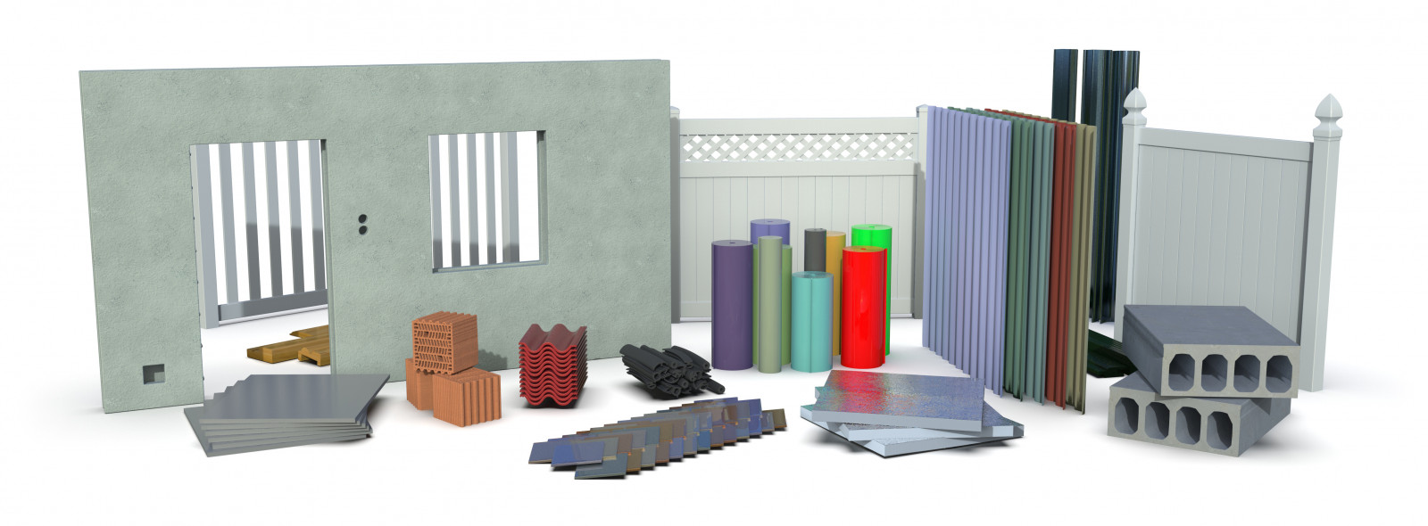
There are many materials you can use to create a frame. As you use more and more materials to build not only robots but other devices, you will get a better feeling as to which is most appropriate for a given project. The list of suggested building materials below includes only the more common ones, and once you have tried a few, feel free to experiment with ones not on the list, or merge some together.
Use existing commercial products

You have likely seen school projects which were based on existing mass-produced products such as bottles, cardboard boxes, Tupperware, etc. This is essentially “re-purposing” a product and has the potential to either save you a lot of time and money or create added hassle and headache. The amazing RoboBrrdto the left is a very good example of how to repurpose materials and make a very capable robot out of them.
Basic construction material

Some of the most basic construction materials can be used to make excellent frames. One of the cheapest and most readily available materials is cardboard, which you can often find for free and can be easily cut, bent, glued, and layered. Example: You can create a reinforced cardboard box that looks a lot nicer and is more proportional in size to your robot. You can then spread epoxy or glue to make it more durable and then paint it.
Flat structural material

One of the most common ways to make a frame is to use a standard material such as a sheet of wood, plastic, or metal, and add holes for connecting all the actuators and electronics. A durable piece of wood tends to be fairly thick and heavy, whereas a thin sheet of metal may be too flexible. Example: A flat ⅛” piece of dense wood can be easily cut with a saw, drilled (without fear of shattering), painted, sanded, and more. You can connect devices to both sides (for example connect the motors and caster wheels to the bottom, and the electronics and battery to the top) and the wood will still remain intact and solid.
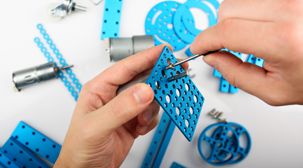
Laser cut / bent plastic or metal
If you are at the stage where you are prepared to have a frame outsourced, the best options are still to have the part precision cut using a laser or water jet. Having a company produce a custom part is ideal only if you are confident in all your dimensions since mistakes can be quite costly. Companies that offer computer-controlled cutting services many also offer a variety of other services including bending and painting.
3D printing

3D printing a frame is rarely ever the most structurally sound solution (because it is built up in layers), but this process can produce very intricate and complex shapes which would not be possible (or very difficult) by other means. A single 3D-printed part can contain all the necessary mounting points for all electrical and mechanical components while saving considerable weight. As 3D printing becomes more popular, the price of producing parts will also go down. A very prominent advantage of 3D printing is not only that your design is easy to reproduce, but it is also, easy to share. For instance, you can click on the turtle shell example on the left and get all the design instructions and CAD files.
Polymorph

Polymorph is really in a class on its own; at room temperature, Polymorph is a hard plastic, but when heated (in hot water for instance), it becomes malleable and can be shaped into intricate parts, which then cools and solidifies into durable plastic parts. Normally, plastic parts require high temperatures and molds, making them off-limits to most hobbyists. Example: You can combine different shapes (cylinders, flat sheets, etc) to form complex plastic structures which look production. You can also experiment with basic molding.
Given the selection of materials and methods, how do you get started? Follow the steps below to create an aesthetic, simple, and structurally sound smaller-sized robot frame.
- Settle on a construction material choice.
- Get all the parts that your robot will require (electrical and mechanical) and measure them. If you don’t have all your parts on hand, you can refer to the dimensions provided by the manufacturer
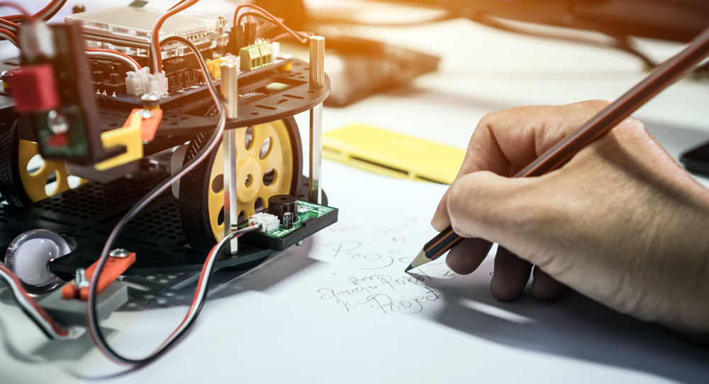
- Brainstorm and sketch a few different designs for the frame. Don’t go into too much detail.
- Once you settle on a design, make sure the structure is sound and that the components would be well-supported.
- Draw each part of your robot on paper or cardboard at 1:1 scale (real size). You can also draw them using CAD software and print them out.
- Test your design in CAD and in real life with your paper prototype by test-fitting each part and connection.
- Measure everything again! and once you are absolutely sure your design is correct, start cutting the frame into the actual material. Remember, measure twice and cut once!
- Test fit each component before assembling the frame in case modifications are required.
- Go crazy and assemble your frame using hot glue, screws, nails, Duck tape, or whatever other binding technique you choose for your robot.
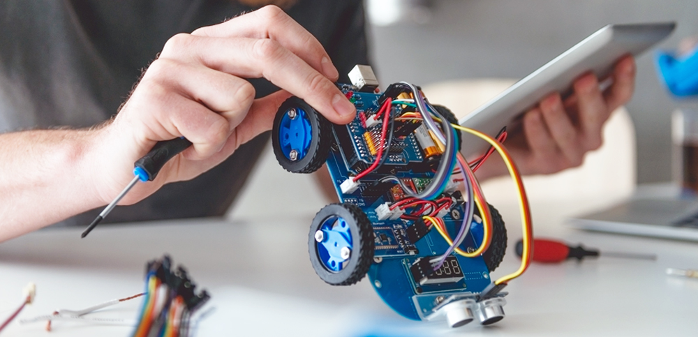
- Fit all the components onto the frame and voila: you have just created a robot from scratch!
Step 10 from the list above deserves to be elaborated upon. In previous lessons, you had chosen the electrical components and actuators. Now, your need to get them all working together. For the following section, we will use generic cable colors and terminal names that only cover the common case. As always, the datasheet and manuals are your bests friends when understanding how robotic equipment works.
Connecting Motors to Motor Controllers
A DC (gear) motor or DC linear actuator will likely have two wires: red and black. Connect the red wire to the M+ terminal on the DC motor controller, and the black to M-. Reversing the wires will only cause the motor to spin in the opposite direction. In a servo motor, there are three wires: one black (GND), red (4.8 to 6V), and, yellow (position signal). A servo motor controller has pins matching these wires so the servo can be plugged directly into it.
Connecting Batteries to a Motor Controller or a Microcontroller
Most motor controllers have two screw terminals for the battery leads labeled B+ and B-. If your battery came with a connector and your controller uses screw terminals, you may be able to find a mating connector with pigtails (wires) that you can connect to the screw terminal. If not, you may need to find another way to connect the battery to the motor controller while still being able to unplug the battery and connect it to a charger. It is possible that not all the electromechanical products you chose for your robot can operate at the same voltage and thus may require several batteries or voltage regulation circuits. See below the usual voltage levels involved in common hobby robotics components:
- DC gear motors - 3V to 24V
- Standard Servo motors - 4.8V to 6V
- Specialty Servo motors - 7.4V to 12V
- Stepper motors - 6V to 12V
- Microcontrollers usually include voltage regulators - 3V to 12V
- Sensors - 3.3V, 5V and 12V
- DC motor controllers - 3V to 48V
- Standard batteries are 3.7V, 4.8V, 6V, 7.4V, 9V, 11.1V and 12V
If you are making a robot with DC gear motors, a microcontroller, and maybe a servo or two, it is easy to see how one battery may not be able to power everything directly. We recommend nevertheless, choosing a battery that can directly power as many devices as possible. The battery with the greatest capacity should be associated with the drive motors. For example, if the motors you chose are rated a nominal 12V, your main battery should also be 12V, then you can use a regulator o power a 5V microcontroller. Without going into details, NiMH and LiPo are the top two choices for small to medium-sized robots. Choose NiMh for a cheaper price and LiPo for a lighter weight. Warning: Batteries are powerful devices and can easily burn your circuits if they are connected incorrectly. Always triple-check that the polarity is right and that your device can handle the energy provided by the battery. If you are not sure, don’t “guess”. Electricity is much faster than you, by the time you realize something is wrong, the magic blue smoke already escaped your device.
Connecting Motor Controllers to Microcontroller
A microcontroller can communicate with motor controllers in a variety of ways:
- Serial: The controller has two pins labeled Rx (receive) and Tx (transmit). Connect the Rx pin of the motor controller to the microcontroller’s Tx pin and vice versa.
- I2C: The motor controller will have four pins: SDA, SCL, V, GND. Your microcontroller will have the same four pins but not necessarily labeled, simply connect them one to one.
- PWM: The motor controller will have both a PWM input and a digital input for each motor. Connect the PWM input pin of the motor controller to a PWM output pin on the microcontroller, and connect each digital input pin of the motor controller to a digital output pin on the microcontroller.
- R/C: To connect a microcontroller to an R/C motor controller, you need to connect the signal pin to a digital pin on the microcontroller.
Regardless of the communication method, the motor controller’s logic and the microcontroller need to share the same ground reference (this is achieved by connecting the GND pins together) and the same logic high level (this can be achieved by using the same V+ pin to power both devices). A logic level shifter is required if the devices don’t share the same logic levels (3.3V and 5V for instance)
Connecting Sensors to a Microcontroller
Sensors can be interfaced with microcontrollers in a similar way to motor controllers. Sensors can use the following types of communication:
- Digital: The sensor has a digital signal pin that connects directly to a digital microcontroller pin. A simple switch can be regarded as a digital sensor.
- Analogue: Analogue sensors produce an analog voltage signal that needs to be read by an analog pin. If your microcontroller does not have analog pins, you will need a separate analog-to-digital circuit (ADC). Also, some sensors come with the required power supply circuit and usually have three pins: V+, GND, and Signal. If a sensor is a simple variable resistor for instance, it will require you to create a voltage divider in order to read the resulting variable voltage.
- Serial or I2C: the same communication principles explained for motor controllers apply here.
Communication Device to Microcontroller
Most communication devices (e.g. XBee, Bluetooth) use serial communication, so the same RX,TX, GND, and V+ connections are required. It is important to note that although several serial connections can be shared on the same RX and TX pins, proper bus arbitration is required in order to prevent cross-talk, errors, and madness in general. If you have very few serial devices, it is often simple to use a single serial port for each one of them.
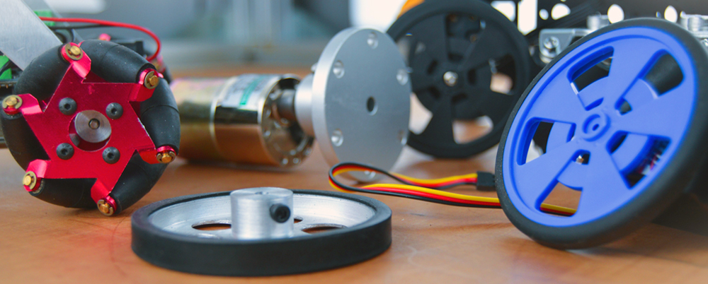
Wheels to Motors
Ideally, you would have chosen wheels or sprockets which are designed to fit the shaft of the motor you chose. If not, hopefully, there is a hub that fits between the two. If you find that the wheel and motor you have chosen are not compatible with one another and cannot find a suitable hub, you may need to find another hub that connects to the wheel but has a smaller bore, you would then drill out the hub’s bore to the same diameter as the shaft.
Electrical Components to Frame
You can mount electronics to a frame using a variety of methods. Be sure that whatever means you use does not conduct electricity. Common methods include hex spacers, screws, nuts, double-sided tape, Velcro, glue, cable ties, etc.
- Settle on a construction material choice.
- We are getting the following parts in order to measure and test fit them:
- 2x Gear motors with 90-degree shafts
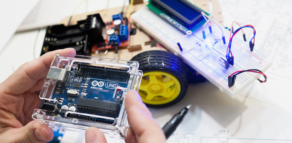
- 1x Arduino Uno
- 1x Johnny Robot Standard GM Track Kit
- 2x Arduino Motor controller Shield
- 2x Mini Breadboard
- We will try to stay close to a 6-sided box, but may have had to make modifications in order to accommodate all parts
- Some modifications need to be done to the design in order to accommodate all parts such as:
- Add more mounting holes for the battery pack
- Add more mounting points for servos or other accessories
- Refined the hole placement.
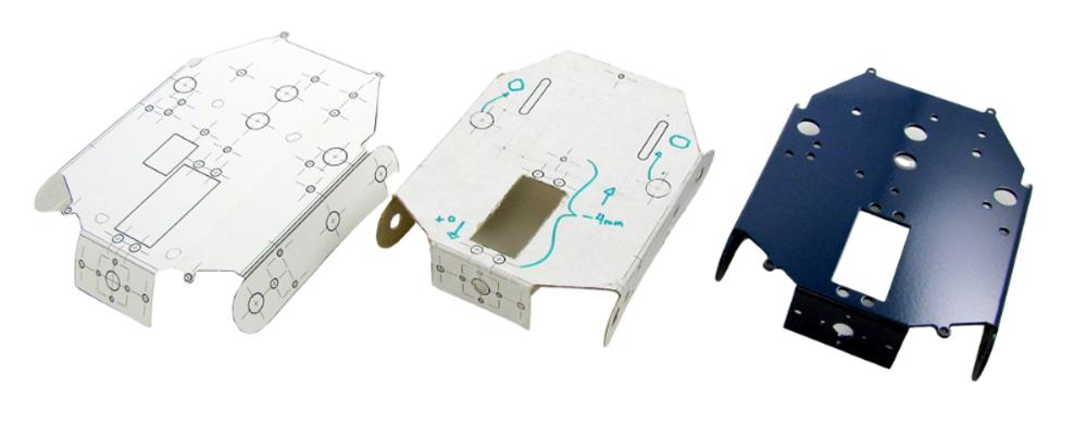
- The cardboard frame will be made by printing the design onto white cardboard (or gluing a printed paper sheet onto cardboard), cutting it, bending it, and using (hot) glue in order to reinforce the bends, edges, and surfaces.
- We completely assembled the robot using the cardboard frame in order to make sure everything fits properly.
- We measure everything again and once we were absolutely sure about the design, we had it professionally manufactured.
- Test fit each component in case modifications are required.
- The frame is made in one piece so no assembly is required
- Assembled the robot incorporating lots of accessories.
For further information on learning how to make a robot, please visit the RobotShop Learning Center. Visit the RobotShop Community Forum in order to seek assistance in building robots, showcase your projects or simply hang out with other fellow roboticists.