


- Lesson 1 – Getting Started
- Lesson 2 - Choosing a Robotic Platform
- Lesson 3 - Making Sense of Actuators
- Lesson 4 - Understanding Microcontrollers
- Lesson 5 - Choosing a Motor Controller
- Lesson 6 – Controlling your Robot
- Lesson 7 - Using Sensors
- Lesson 8 - Getting the Right Tools
- Lesson 9 - Assembling a Robot
- Lesson 10 - Programming a Robot
What is a microcontroller?
You might be asking yourself what is a microcontroller and what does it do? A microcontroller is a computing device capable of executing a program (i.e. a sequence of instructions) and is often referred to as the “brain” or “control center” in a robot since it is usually responsible for all computations, decision-making, and communications. In order to interact with the outside world, a microcontroller possesses a series of pins (electrical signal connections) that can be turned HIGH (1/ON), or LOW (0/OFF) through programming instructions. These pins can also be used to read electrical signals (coming from sensors or other devices) and tell whether they are HIGH or LOW.

Source: Vishnu Mohanan - Unsplash
Most modern microcontrollers can also measure analog voltage signals (i.e. signals that can have a full range of values instead of just two well-defined states) through the use of an Analogue to Digital Converter (ADC). By using the ADC, a microcontroller can assign a numerical value to an analog voltage that is neither HIGH nor LOW.
Although microcontrollers can seem rather limited at first glance, many complex actions can be achieved by setting the pins HIGH and LOW in a clever way. Nevertheless, creating very complex algorithms (such as advanced vision processing and intelligent behaviors) or very large programs may be simply impossible for a microcontroller due to its inherent resource and speed limitations. For instance, in order to blink a light, one could program a repeating sequence where the microcontroller turns a pin HIGH, waits for a moment, turns it LOW, waits for another moment, and starts again. A light connected to the pin in question would then blink indefinitely. In a similar way, microcontrollers can be used to control other electrical devices such as actuators (when connected to motor controllers), storage devices (such as SD cards), WiFi or Bluetooth interfaces, etc. As a consequence of this incredible versatility, microcontrollers can be found in everyday products. Practically every home appliance or electronic device uses at least one (often many) microcontrollers. For instance TV sets, washing machines, remote controls, telephones, watches, microwave ovens, and now robots require these little devices to operate. Unlike microprocessors (e.g. the CPU in personal computers), a microcontroller does not require peripherals such as external RAM or external storage devices to operate. This means that although microcontrollers can be less powerful than their PC counterpart, developing circuits and products based on microcontrollers is much simpler and less expensive since very few additional hardware components are required. It is important to note that a microcontroller can output only a very small amount of electrical power through its pins; this means that a generic microcontroller will likely not be able to power electrical motors, solenoids, large lights, or any other large loads directly. Trying to do so may even cause physical damage to the controller.
Special hardware built into the microcontrollers means these devices can do more than the usual digital I/O, basic computations, basic mathematics, and decision-making. Many microcontrollers readily support the most popular communication protocols such as UART (a.k.a. serial or RS232), SPI, and I2C. This feature is incredibly useful when communicating with other devices such as computers, advanced sensors, or other microcontrollers. Although it is possible to manually implement these protocols, it is always nice to have dedicated hardware built-in that takes care of the details. It allows the microcontroller to focus on other tasks and allows for a cleaner program. Analog-to-digital converters (ADC) are used to translate analog voltage signals to a digital number proportional to the magnitude of the voltage, this number can then be used in the microcontroller program. In order to output an intermediate amount of power different from HIGH and LOW, some microcontrollers are able to use pulse-width modulation (PWM). For example, this method makes it possible to smoothly dim an LED. Finally, some microcontrollers integrate a voltage regulator in their development boards. This is rather convenient since it allows the microcontroller to be powered by a wide range of voltages that do not require you to provide the exact operating voltage required. This also allows it to readily power sensors and other accessories without requiring an external regulated power source.
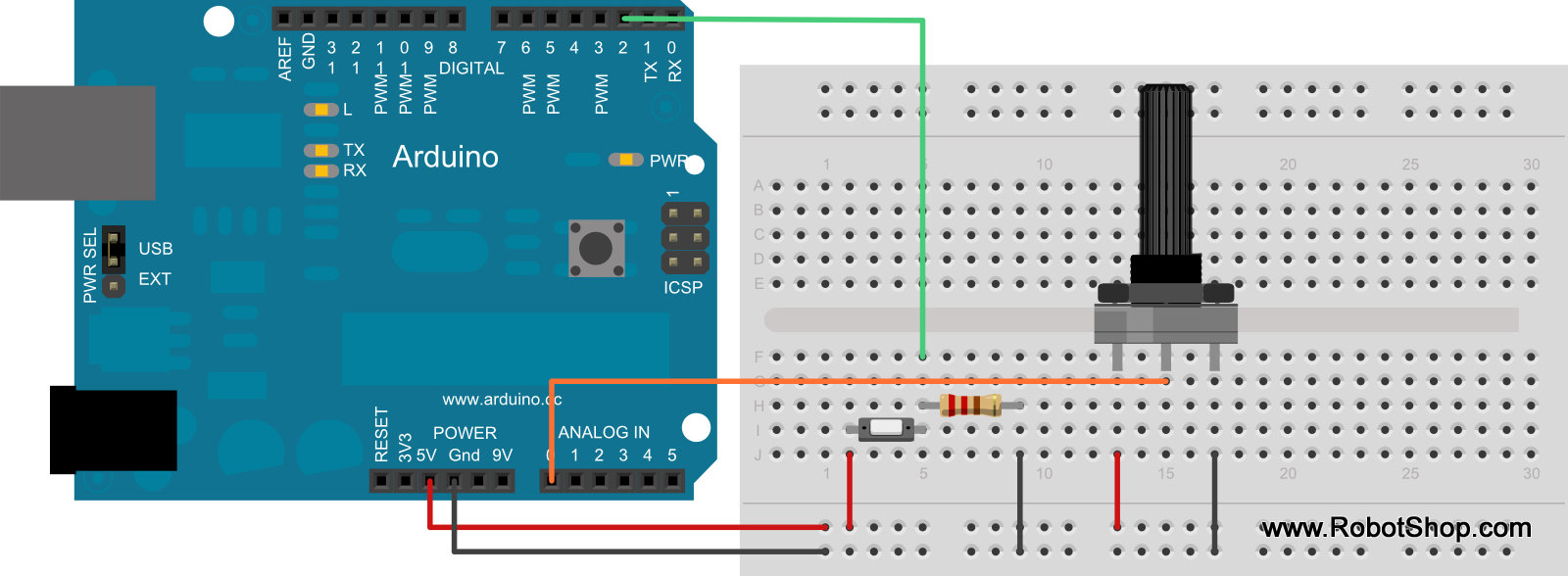
Below you can find two examples that illustrate when to use a digital or analog pin:
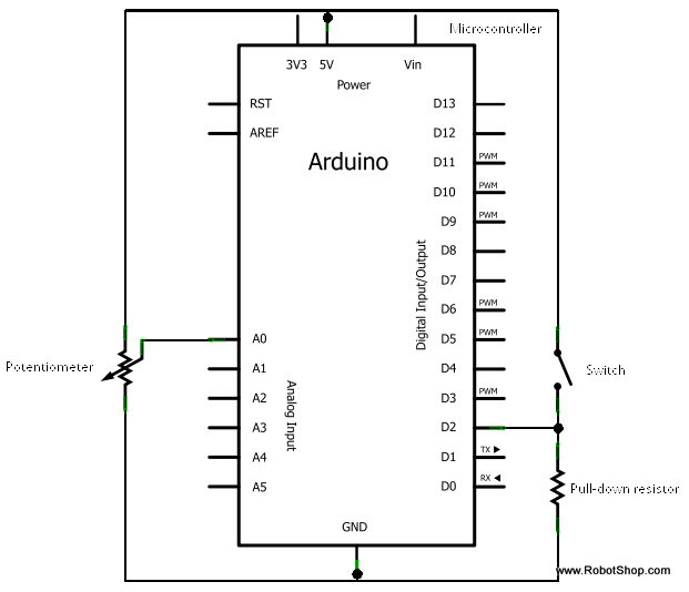
- Digital: A digital signal is used in order to assess the binary state of a switch. As illustrated below (on the left side of the solderless breadboard), a momentary switch or push button closes a circuit when pressed, and allows current to flow (a pull-up resister is also shown). A digital pin connected (through a green wire in the picture) to this circuit would return either LOW or 0 (meaning that the voltage at the pin is in the LOW range, 0V in this case) or a HIGH (meaning the button is pressed and the voltage is at the HIGH range, 5V in this case).
- Analog: A variable resistor or potentiometer (as shown towards the right side of the board below) is used to provide an analog electrical signal proportional to a rotation (e.g. the volume knob on a stereo). As illustrated below, when a potentiometer is connected to a 5V supply and the shaft is turned, the output will vary between 0 and 5V, proportionally to the angle of rotation. The ADC on a microcontroller interprets the voltage and converts it to a numeric value. For example, a 10-bit ADC converts 0V to the value “0”, 2.5V to “512” and 5V to “1023”. Therefore if you suspect the device you plan to connect will provide a value that is proportional to something else (for example temperature, force, position), it will likely need an analog pin.

Being afraid of programming microcontrollers is getting old-fashioned. Unlike the “old days” when making a light blink took advanced knowledge of the microcontroller and several dozen lines of code (not to mention parallel or serial cables connected to a huge development board), programming a microcontroller is very simple thanks to modern Integrated Development Environments (IDE) that use up-to-date languages, fully featured libraries that readily cover all of the most common (and not so common) action, and several ready-made code examples to get beginners started. Nowadays, microcontrollers can be programmed in various high-level languages including C, C++, C#, Processing (a variation of C++), Java, Python, .Net, and Basic. Of course, it is always possible to program them in Assembler but this privilege is reserved for more advanced users with very special requirements (and a hint of masochism). In this sense, anyone should be able to find a programming language that best suits their taste and previous programming experience. IDEs are becoming even simpler as manufacturers create graphical programming environments. Sequences that used to require several lines of code are reduced to an image that can be connected to other “images” to form code. For example, one image might represent controlling a motor and the user need only place it where he/she wants it and specify the direction and rpm. On the hardware side, microcontroller development boards add convenience and are easier to use over time. These boards usually break out all the useful pins of the microcontroller and make them easy to access for quick circuit prototyping. They also provide convenient USB power and programming interfaces that plug right into any modern computer. For those unfamiliar with the term, a Development Board is a circuit board that provides a microcontroller chip with all the required supporting electronics (such as voltage regulators, oscillators, current limiting resistors, and USB plugs) required to operate. If you are not planning to design your own support circuit, buying a development board is preferable to simply get a single microcontroller chip.
Note: Robot programming is covered in greater depth in Lesson 10.
It is apparent that a microcontroller is very similar to a PC CPU or microprocessor, and that a development board is akin to a Computer motherboard. If this is the case, why not simply use a full computer to control a robot?
As a matter of fact, in more advanced robots, especially those that involve complex computing and vision algorithms, the microcontroller is often replaced (or supplemented) with a standard computer. A desktop computer includes a motherboard, a processor, a main storage device (such as a hard drive), video processing (on-board or external), RAM, and of course peripherals such as a monitor, keyboard, mouse, etc. This type of system is usually more expensive, physically larger, and more power-hungry. The main differences are highlighted in the table below.
| Microcontroller | Personal Computer | |
| Example | Atmega328 | Intel Pentium Core 2 Duo |
| RAM | 1KB | 4000000KB (4GB) |
| Storage | 15KB | 15000000KB (1000GB) |
| Power | 0.1W | 600W |
| Voltage | 12 | 12 |
| Input/Output | Pins | USB, RS232 |
| Wireless | Bluetooth*, RF* | Bluetooth |
| Video | None | 1000000KB (1GB) |
| Price | $4 to $300 | $400 to $2000 |
| Internet | WiFi* or Ethernet* | WiFi or Ethernet |
| *Available as optional additions on many microcontrollers. |
Unless you are into BEAM robotics or plan to control your custom robot using a tether or an R/C system (which, based on our definition from Lesson 1 would not be considered a robot), you will need a microcontroller for any robotic project. For a beginner, choosing the right microcontroller may seem like a daunting task, especially considering the range of products, specifications, and potential applications. There are many different microcontrollers available on the market: Arduino, Raspberry Pi Pico, ESP32, Parallax, and more. When considering the right microcontroller, ask yourself the following questions:
- Which microcontroller is the most popular for my application? Of course, making robots or electronic projects, in general, is not a popularity contest, but the fact that a microcontroller has a large supporting community or has been successfully used in a similar (or even the same) situation could simplify your design phase considerably. This way, you could benefit from other users’ experience and among hobbyists. It is common for robot builders to share results, code, pictures, videos, and detailed successes and even failures. All this available material and the possibility of receiving advice from more experienced users can prove very valuable.
- Does it have any special features the robot requires? As popular as a microcontroller might be, it must be able to perform all the special actions required for your robot to function properly. Some features are common to all microcontrollers (e.g. having digital inputs and outputs, being able to perform simple mathematical operations, comparing values, and taking decisions), while others need specific hardware (e.g ADC, PWM, and communication protocol support). Also, memory and speed requirements, as well as pin count should be taken into consideration.
- Are the accessories I need available for a particular microcontroller? If your robot has special requirements or there is a particular accessory or component that is crucial for your design, choosing a compatible microcontroller is obviously very important. Although most sensors and accessories can be interfaced directly with many microcontrollers, some accessories are meant to interface with a specific microcontroller and even provide out-of-the-box functionality or sample code.
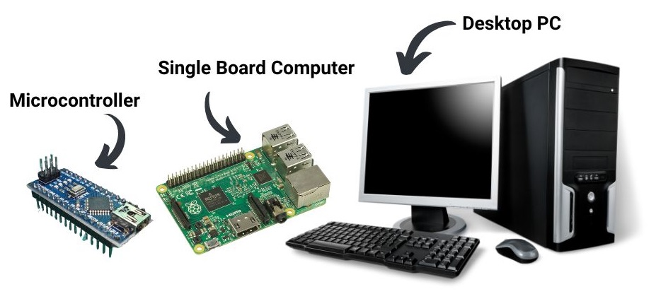
As the price of computers has gone down, and advances in technology make them smaller and more energy efficient, single-board computers have emerged as an attractive option for robots. These single-board computers (like the popular Raspberry Pi) are essentially all-in-one computers you may have used about 5 years ago, and incorporate many devices into one circuit board (so you cannot swap anything out). They run a complete operating system (Windows and Linux are most common) and can connect to external devices such as USB peripherals, monitor(s), cameras, and more. Unlike their ancestors, these single-board computers tend to be much more power efficient and easily used in mobile robot applications. Although the price of single board computers is dropping to the point where they are almost on par with microcontroller boards, for practical purposes, we suggest only considering using a single board computer for more advanced needs like adding a camera system, full monitor output, running multiple services, etc. and start with a good microcontroller for ease of use.
In order to choose a microcontroller, we compiled a list of features/criteria we wanted:
- The microcontroller’s cost must be low while including a development board (below 50$)
- It must be easy to use and well-supported. It is also important to have lots of documentation readily available.
- It should be programmed in C or a C-based language.
- It must be popular and have an active user community.
- Since the robot will be used as a general-purpose platform, the microcontroller should be very feature-rich in order to allow for broad experimentation. In this sense, it should have several analog and digital pins, as well as an integrated voltage regulator.
Since our robot will use two motors, the microcontroller will need two digital pins for direction control, and two PWM pins for speed control (this will be explained in more detail in Lesson 5). The robot will also transmit and receive data so it will need to support the UART (a.k.a. serial or RS232) communication protocol in our case. We would also like the option of adding other sensors and devices in the future so analog pins and many extra digital pins would be appropriate. The upcoming RobotShop Microcontroller comparison table allows us to compare the main features of one microcontroller with another. The Pololu and Arduino microcontrollers seemed to conform best to the above criteria. In order to select a specific microcontroller from these two manufacturers, each was researched in order to determine the amount of available material, code, user community, Google hits, and more.
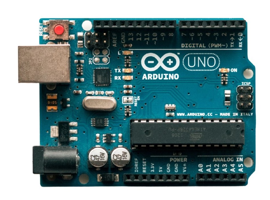
The Arduino Uno was ultimately chosen based on price vs. features and because of the concept of “shields” (separate accessory boards you plug and stack onto the microcontroller which adds specific functionality). Also, Arduino is rather popular, there are many sample projects, and its community is very active.
For further information on learning how to make a robot, please visit the RobotShop Learning Center. Visit the RobotShop Community Forum in order to seek assistance in building robots, showcase your projects or simply hang out with other fellow roboticists.