


Now that we have talked about the requirements, the code, and all the things you need to know about the project, we can start setting everything up. First, we need to make sure everything is working properly, to do this we suggest checking the LSS 4DoF Arm Quick Start Guide and in case you have the kit version a nice tip is to set the ID of each servo before assembling the arm, when you’re updating the firmware for example, and it is also advisable to mark the servos with the provided stickers at this stage.
Also, if this is also the first time you’ll be using a Raspberry Pi we also recommend checking the Setting up your Raspberry Pi Introduction and the Getting started with the Camera Module Introduction. If everything is working as expected you can now connect the LSS Adapter Board to the Raspberry Pi and run the test program available in the Using the Lynxmotion Smart Servos with a Raspberry Pi tutorial. Note that this example works for the base rotation servo (ID = 0) only but you can modify the code to test the other servos as well.
After testing all the electronics, we can set up the rest of the hardware in a location with stable lighting. If you haven’t already, go ahead and assemble the arm and attach it to a stable fixture. We used screws to attach it to a wooden board, on which both the arm and the chessboard fitted, but if you can't do this you could use some heavy-duty double-sided tape so that it doesn't move from its position. The base of the arm has to be placed as close to the chessboard as possible and it needs to be centered with respect to the middle of the board.
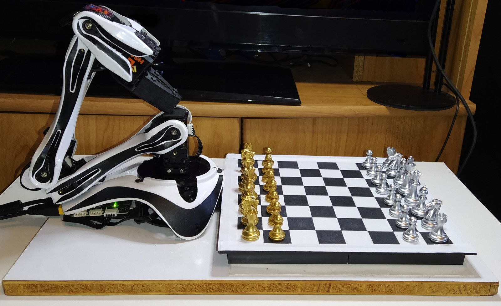
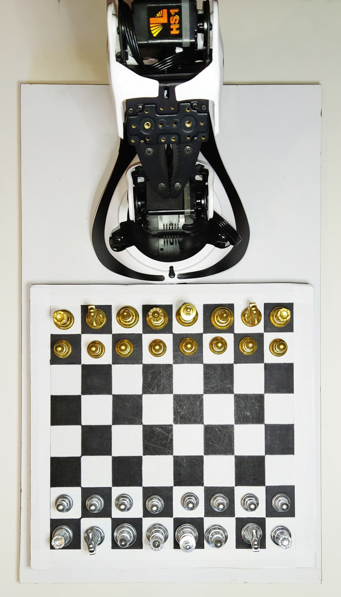
As previously mentioned, the computer vision algorithms work best if the chess board and pieces have contrasting colors. In this tutorial, we used a black and white chessboard with silver and gold pieces, but we recommend using a checkerboard calibration target with a matte finish. The camera module needs to be high above the center of the chessboard to avoid distortion, caused by the edges of the board being farther away from the camera than the center of the board, and to prevent the chess pieces from obstructing adjacent squares. If you are not sure of how well the camera is positioned, don't worry, at the start of the game the GUI allows you to see the video captured by the camera so you can calibrate it.
You need to place the camera and lights so that there are as few shadows as possible and you also need to ensure that they won't move during the game, so they have to be fixed firmly. As mentioned in the requirements tutorial, we will use a CSI to HDMI Module to extend the camera with a HDMI cable, to install it you can follow the assembly instructions available in the product’s manual. To make the combination of these two modules more aesthetic we 3D printed a case, if you are interested in it you can find the model here (if you have a module with an audio jack you might need to make some modifications to the case). And as the lightning setup used in this tutorial is a ring light we printed an additional piece to adjust that case to the center of the light so the camera placement doesn’t produce any shadows.
If you want to hear the robot’s comments you can connect a speaker to the Raspberry Pi, but this is optional. We used a Bluetooth speaker but we actually connected it using the audio jack. If you connect it through the audio jack or HDMI you can follow this tutorial to check if it is working properly, and if you want Bluetooth connection you can follow this one.
Finally, we need to build the project, you can find all the steps listed in the Github Repository. There you will also find a requirements file that lists all the python packages needed for the project and in case this is the first time you're installing python packages in your Raspberry Pi this tutorial might come in handy Using pip on Raspberry Pi Introduction.
And now, we are ready to play chess! Here's a short demonstration of a game with our robotic friend.
And you can find the whole playlist here.
This project is implemented for the LSS 4DoF Robotic Arm which user-calibrated, and the code is currently calibrated for my robotic arm in particular, and as such you need to set the inverse kinematics constants to match your arm. While the joint lengths may be the same (measured from rotating axis to axis, not end to end), the servo angles may vary between implementations. It is recommended for this project that instead of calibrating all the servos at the same time with the LSS FlowArm app each servo should be calibrated individually with the LSS Config app. This will make a big difference in the arm’s positional accuracy.
Another important recommendation is that when playing, you should wait for the robot to finish its move before doing yours, that is, wait for the arm to return to the rest position. Otherwise, the image taken to detect the movements of the pieces can be affected by the obstacles causing an error in the detection of the user’s move.