I have a robot that has 10 servos (2 arms) and uses the SCC-32U controller with a Raspberry Pi 3+ for control and communications. I would like to use two inputs from user, using the split command, to substitute into a sp.write statement to move servos, i.e., sp.write("#7 P1500S200\r".encode()).
This is what I have so far:
import serial
sp = serial.Serial(’/dev/ttyUSB0’, 9600)
while True:
var1, var2 = [int(x) for x in input("Enter servo # & servo position here: ").split()]
print(var1, var2)
sp.write("#(var1) P(var2)S200\r".encode())
When running the code accepts user input (ex.–7 1200) and correctly prints out line 5 but does not move servo 7 in line 6. Results in a “string” error and stops program.
-7 does not feel like it should be an acceptable input since negative channel numbers are not valid. The valid range for #n is [0, 31].
For line 5, change:
print(var1, var2)
to:
print("#(var1) P(var2)S200\r".encode())
Let me know what it prints instead if you use this updated line above.
Have a look at the example found here.
The way I print out my strings mixed with variables is different than yours. And I’m pretty sure it works well when I tested it back then (and other people used it to). Have a look and see if that helps!
The print statements are correctly printing out the inputs (ex. 7 1500 for servo number and servo position). As per you suggestion I change the sp.write statement to:
sp.write(("#" + var1 + " P" + var2 + “S200” + “\r”).encode())
I also tried sp.write(("#" + str(var1) + " P" + str(var2) + “S200” + “\r”).encode())
Both resulted in the following error message:
pi@GMArm:~ $ python test.py
Enter servo # & servo position here: 7 1500
Traceback (most recent call last):
File “test.py”, line 30, in
var1, var2 = [int(x) for x in input("Enter servo # & servo position here: ").split()]
File “”, line 1
7 1500
^
SyntaxError: unexpected EOF while parsing
I think we are close but not yet quite there. You thoughts please?
By the way, controller is work fine when receiving correct write statement such as:
sp.write("#7 P1500S200\r".encode()) # Rt elbow servo
Line 30 is the line asking for user input. I input as "7 space 1500.
Hey @RoboNovice! Thanks for the extra details. I’m a bit confused now so please help me along:
1)
Those three parts of your post, after reading them a few times, make me think this: the print works, but it happens after the input that crashes?
That is the part that confuses me…
I’ll have a look at making this work here then and see what’s up!
I’m getting some hardware to test it shortly, so for now I’ll do a “software test” of it without an actual board connected to the port (though I have a logic analyzer hooked up to the UART side, so that’s all good; I’ll still see the outputs! ).
Once I have something working, I’ll attach a version here as a .py (inside a .zip, forum policy).
I have gotten it to work when I assign two separate inputs to variables (ie. num and pos). But would be better to be able to enter both in one step using the split function. The final script’s purpose is to be able to move any of the 10 servos to varying positions, one and a time and also have seven presets with multiple moves to dock and undock each arm, un-power each or both arms. See attach file. finalarms.zip (900 Bytes) . The position will work with single variables but have not got the preselects to work yet.
So, aside from taking the two inputs separately any other big changes?
That is a great idea and probably super convenient!
Checking now!
Hmm… maybe I should post here the other piece of code I made after I got the one based of your example working… let me clean it up and I’ll upload it here shortly!
Another quick question, the SSC-32U board specs states “VS steady current: max 3-5 amps per side recommended”, does that mean a side is connectors 0-15 and the other side 16-31?? If so, it might explain my overheat problem when all 10 powered on side 0-15???
Yes, it does mean exactly that. VS1 is connected to one side, VS2 to the other.
By default though, VS1=VS2 jumpers are in place to connect the two sides.
Most likely, yes.
I highly recommend you do the following:
Remove the VS1=VS2 jumpers. Store them somewhere safe so you don’t lose them!
Connect each arms’ RC servomotors to a different side (i.e.: one on 0-15 and one on 16-31).
Connect a power supply of 6 V DC to each side through VS1 and VS2.
Side note, VS1 is the channel used to power the regulator for the on-board electronics. If you have higher current demands on one arm than the other, place the higher current use one on VS2 / channels 16-31 to reduce risks of electrical issues such as brownouts of the SSC-32U.
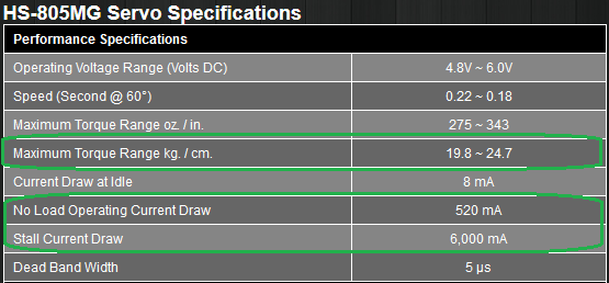
I am driving the shoulder joint of my robot with a Hitec HS-805MG servo. I am still having issues with moving the arm shoulder joint, probably due to weight of arm. Do you have a suggestion for a better way to drive this joint; i.e. increasing torque, using motor versus servo, etc. Suggestions welcome. Thanks.
Well, you could also reduce the load on that joint, too.
As for increasing torque, that would require modifying the joint, such as replacing the servo with a stronger one or adding gear-down ratio to increase effective torque but reduce speed.
A (in this case RC) servo motor is an actuator made from a motor, typically a DC motor.
The best place to start when asking for suggestions is to give more info about the project and the goal(s):
What kind of robotic arm(s) are you using? Maybe give out a link, pictures, specs, etc.
What are you trying to do with said robotic arms?
Once you provide this info it will be easier to give you advice.
So attached are pics of robot and arms assembly. The arms are 50 cm long and have not weighed them but maybe up to two pounds each with most of that weight in shoulder and upper arm. The shoulder only moves about 120 degrees of motion. Would not be lifting anything too heavy but all of that weight would be at the end of the 50 cm. Servos are connected to 6V 7aH battery driven with the SCC-32U and running Python through the Raspberry Pi 3+.
Because of the limited movement, but heavy torque load, I chose to go with the analog servos. Would something like the RB-Lyn-990 work and can I control it with the SCC-32U as well as the other analog servos or something more like a brushless DC motor/encoder?
An online calculator might be helpful, too, such as this one. @cbenson can probably provide better info concerning that aspect of design.
At the very least, I recommend making a sketch of your one robot arms and try and determine the worst case load (static/gravity) to at least get an idea of the kinds of loads imposed on each joint and what torque will be required. Without that information I can’t really say what motors will work since I don’t know what they will be lifting.
For the sketch, maybe use something along the lines of this (link here; feel free to request a copy from there):
With this detailed info you’ll be able to better assess what torque is required where and therefore choose the best servo motor for the job instead of using trial and error.
Whether the servos are analog or digital won’t make much of a difference overall. Through on the more expensive side digital servos are more likely to outperform analog servos, especially concerning possible configurations and adjustments possible.
It may. This really depends on the info above concerning loads, torques, etc. Though considering the size and weight of your arm I’d probably use at the very least a power gearbox to increase torque and maybe even put two motors in the joints further from the end point (such as shoulder and maybe even the elbow).
The LSS can be controlled in RC PWM mode, yes.
The one caveat here is that LSS are at peak condition/capability at 12 V DC (also the recommended voltage) whereas most of your RC servomotors use 6 V DC, sometimes (but rarely) 7.2-7.4 V DC. The best in this case would be to either:
Remove VS1=VS2 and connect all 6 V DC servos on one side and the 12 V DC LSS on the other, with appropriate voltage sources on each side. Since you are likely already doing this to split the 10 servos in two groups, this is probably not the best solution.
Leave both sides connected to 5 servos but when you connect the LSS only use the signal (yellow/white) and ground wires (black). Remove the VCC wire (red) from the connector (shouldn’t be too hard to push it out from the side). Then, connect the LSS through their other connector (2 on each LSS) to the proper power source using a LSS cable and a power hub. This way you can have 12 V DC feed the LSS while controlling the signal from the SSC-32U.
Of course, either of these solutions carry the risk of burning parts if you are not careful. I highly recommend to use great care and have a multimeter handy nearby. Test all end points (for voltage with reference to the common ground) before making any connections. Test again before connecting the RC servomotors or the LSS.
Not a bad idea in general but far less trivial. This means you won’t be able to use the SSC-32U and will instead have to build your own DC motor controller. I recommend not doing so as it is quite a bit of a project in itself and most likely out of scope for yours.
So without any payload at all, it seems like both your upper arm and shoulder spacer joints need > 30 kg-cm of torque under normal conditions.
If you consider adding payloads, something as light as a small 100 g object at ~47 cm distance from the first joint (shoulder) adds a requirement of over 4.7 kg-cm to it! If we assume the object is not perfectly at 47 cm (lets use 50 cm), that’s roughly +5 kg-cm requirement per 100 g of payload desired/used.
Of course, all of this is the static case (i.e.: you hold the arm straight ahead and power it to stay there). Getting to that position will require a higher peak torque to beat inertia and start motion.
Typically, the rule of thumb I use for scoping motor specs for a specific application is to expect the continuous load (here we can use your “worst case” static load as reference/base case) to be about 20-25% of the motor’s stall torque.
Therefore, if your joint (ex: shoulder) needs 35 kg-cm to hold the static load you’d want a motor that can provide 4-5 times that amount at peak capability. In your case that would be 140-175 kg-cm. And for that shoulder joint for each 100 g of payload you wish to add, you need to add 20-25 kg-cm (from that 5 kg-cm calculation above) of stall torque to the requirements for the motor.
Since you are using the HS-805MG, please note the following caveats here:
The motor you currently use cannot provide enough torque at stall (when it stops moving and eventually burns up and dies if it stays there too long) to meet your requirements of ~31 kg-cm, let alone with an extra potential payload (see numbers above).
To be fair, you can have a motor function above 20-25% continuously / near the stall torque (but not above). This does have some critical implications for your application though:
The motor in question will overheat quickly and will probably need breaks between tasks (to cool off), the tasks themselves need to be short and active cooling may be required.
The longevity of the motor in question will be significantly shortened since it is always at or near its max capability.
The closer you are to stall torque the less efficient (more power in [electrical] > power out [mechanical]) and the slower your motor will move.
All things considered, I highly recommend that you either seriously beef up the two problematic joint’s motors; either more powerful motors, double them up, add gear-down or a combination of those ideas.
So I have purchased two continuous rotation gearboxes using the Hitec HSR-M9382TH servo for the shoulder joints. I believe I can control these with the SSC-32U board?? That way I can also power them with the same 6v power supply. Can you direct me to information about how to program/control these servos?? Thanks
What type of gearbox is it (composition, style, ratio, etc.)? Do you have a link to the product?
From the specs of that servo, you’d probably want a gearbox with at least 4:1, maybe 5:1 ratio to keep that RC servomotor operating in a nice range. Also, from that I understand, this servo can also be reprogrammed to do more than 1 turn which is great for use with a gearbox.
The SSC-32U can send control signals to any RC servomotor.
My program/control do you mean change the RC servomotor’s settings (i.e.: change their behavior) or simply make them move?
If it is the former, most people typically use a USB programmer for those servos made by the manufacturer. That is usually the simplest way. Some other distributors claim this one can do it, but the official documentation doesn’t specify the HSR series as compatible (or not).
If it is the latter, you can simply use what we discussed before in this topic (using Python).