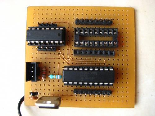
This is my picaxe 20m2 dev board. It has picaxe itself, a LM7805 voltage regulator and two DIL sockets, one for ULN2803 and the other for L293d (already in place). Those four copper wires (I know that looks a little unusual but there wasn't any other way in which i could connect picaxe with L293d :P) in the above photo are going from the output pins of the picaxe to the input pins of L293d.And I am using three polarised male headers set instead of that usual 3.5 mm jack for the programming purposes cause I think that 3.5mm female connector is a lot more space consuming.
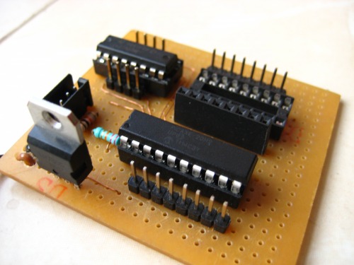
Another picture.
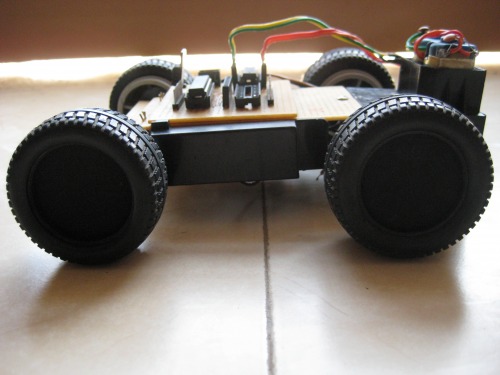
Here's the basic platform that i'll be working on in some of my starting robots. It has two geared motors (one for each side) which enables it to move.I choose this tank mechanism so that I can upgrade to tracks later on (I am working on making my own tracks). I have used a perf board to make the main chassis cause it is easier to add more components like proximity sansors, robotic arm etc. later (i can use male headers to keep the extra components in place). The batteries are positioned underneath the perf board.
.Here's another picture
Comments, suggestions, advices are welcome.
Thank You :)
Navigates around
Actuators / output devices: two geared motors (221:1)
Right now, I have programmed it to just to go ahead for two seconds, turn around, return and keep repeating the same. I’ll post a video soon when i add a proximity sensor on it.
I made my Start Here Robot (sort of) on this, it has an IR proximity sensor in place of that sharp ir sensor and it just turns around in ‘one’ fixed direction if something comes ahead it.
I got the rear gear box from an old 4x4 bulldozer toy and made my main chassis with a perf board as it provides a large area for holding electronics and other stuff, and it also makes it easier to keep those electronics in place as i have soldered male headers on it according to my picaxe board’s size and it fits nicely :)
There is no reason you can’t run a bot from a '628.
It, the 16f628, has fewer pins, so, you would need to adjust where things are connected. Otherwise, it is a matter of adding a motor driver, and, having the option to add a darlington array to 7 or 8 pins. There are robots posted here that run from 8 pin PICAXE(PIC) chips. Adding pins just makes it easier to add components.
Sorry, but i can’t. I don’t have any schematics or PCB design for it, i just made it according to my needs but i do can provide you some high res pictures of the board from below if you want
First of all, which microcontroller are you using? If you are using a PIC then this schematic will not work with it and you will need a different circuit which will depend on the I/O pins on your PIC. see this nice little breadboard module if you are using a PIC16F628A- http://embedded-lab.com/blog/?p=1034 .
Secondly i used a USB-Serial cable when i was using picaxe and this board and you only need three wires to program a picaxe ie. serial out (tx), serial in (rx) and ground (0V). that is why i have shown a three wire connector in my schematic. If you are using a PIC then you will probably need a PIC programmer (for example a PICkit 3). and i can’t help you with those five wires untill you describe the place from where those wires are coming from (it can be a programmer as well as a USB to serial convertor).
At the time i made this post it was programmed to just move ahead for two seconds, then turn left and then again go ahead for two seconds and so on… after some time my programming cable went bad and since then i have never used picaxe again. But i do have a code for a simple obstacle avoider i wrote when i started with picaxe that ran perfectly on this-
a proximity sensor is fixed ahead of the car and its output (connected to pin c.7 of picaxe 20m2) goes high when something comes too near to it, then it turns left and starts moving again…
pause 2000
main: if pinc.7=1 then gosub turn else gosub ahead end if goto main