Meet "Walter"

Thanks to the naming genius of GroG... I now proclame thee Walter!


***Major Update 11.16.08***

First test worked perfectly! Even with bad code. The motors came on a little suddenly and I didn't have a good 0 to Full-speed range (code problem) but the basic system is solid. Now that I know everything works, I need to do a total tear-down and start figuring out where everything is going to go. Now, God doesn't open a window without closing a door so it seems that this guy will be taken down and will be donating its boards and sensors:

So there you go! Again, I want to give much thanks to everyone who has given me a hand on this one, from motor control and FET's to EEPROM's and all else. I will keep up with the updates as I go but for now, I have a lot of work just changing the initial MacGyvered set-up (in the video) to a proper one. Then comes the rest!


***Update 11.15.08***

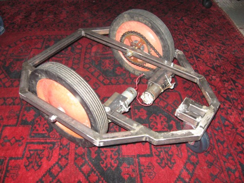
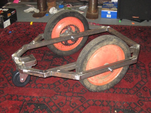
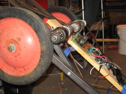
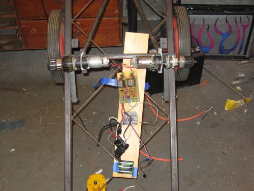
Both drive systems done and installed! You would not belive the torque coming out of the wheels! Both motors are mounted with slotted holes allowing adjustment and tentioning of the drive chains. I am doing the electronic work tonight, maybe I'll have a "driving around" video tomorrow.


***Update 11.14.08***

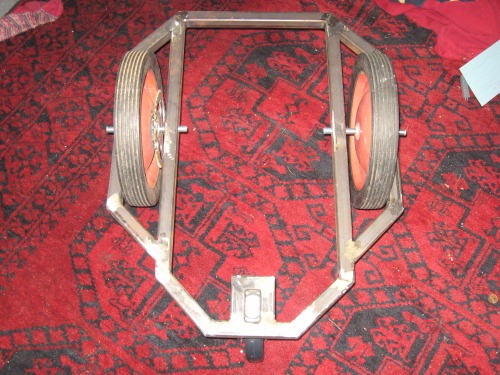
The Frame is Done!!!

(I added a picture with my boy, Charlie-Mac for an idea of scale)


***Update 11.9.08***

Huge Score, folks!!!

I ran into 2 old-school garage door openers and scored 2 small sprockets! Better than that, the ID was just a tiny bit smaller than the shaft comming out of my drill motor. I was able to run a tap down the middle and thread the inside of the gear to the same threading of my drill! --I also drilled and tapped 2 smaller holes for set-screws to lock it to the shaft! PERFECT!

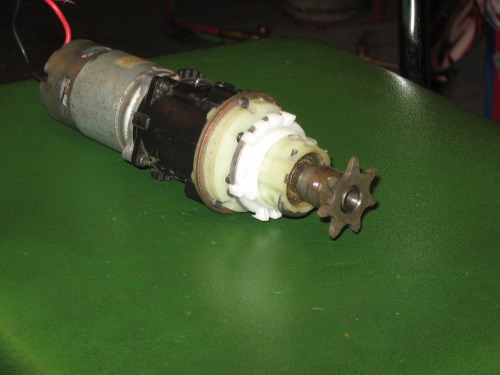
Score number two: I found that the chain used for the garage door opener is not only 15' long, contains TWO master links but is the same pitch as a standard bicycle!!!! Off to the salvage shop. For free I scored 2 kids bikes both with 36 tooth main sprockets. I have liberated them and well, here we go:

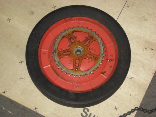
So here's what we got: 2 complete chain-drive systems, with a final gear ratio of 36:6 or 6:1. Not only is this the cleanest possible set-up I can think of but with both drills in low and another 6:1 on top of that, this thing will be able to climb a tree! --One more, I was looking at the shift mechanism on the drills... it seems quite easy and possible that a servo could be used to switch from low to high. Just think about it, the first bot here with a REAL transmission including shift-on-the-fly from "wicked fast" to "wicked torque"... OH YEAH!!


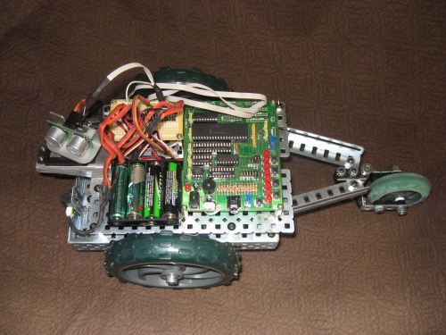
I know I should wait until I have video of this guy cruising around on the ground but I couldn't wait.

The frame is from a previous project I did and the drive method is a joke --I mean, c'mon two wheels just rubbing on eachother? The drive system on the final bot will, of course, be a belt and pulley or chain/ sprocket. For now, I am still working on the code and being sure it is "friendly" to the motor driver board. I am still suprised how sensitive these FET's can be.

As you can see on the video, I am just running a simple code of Fwd, spin right, spin left and rev. I am using the PWM code and "ramping up" and "ramping down" the speed before and after any and all changes in direction. I will have to play with it a while to see exactly what I can throw at the controller without smoking anything. For now, I have a 20A inline fuse for the main protection and I have yet to blow it. --However, I have not yet done a test with the wheels on the ground.

You can keep up with the video by watching the LED's on the board... The 2 greens are the PWM signal A/B and the reds indicate a reverse for that side.

Here's just a couple pics:


  • Actuators / output devices: 2 DeWalt 12V drill motor / transmissions
  • Control method: BOA's motor controller
  • Power source: 14.4V DeWalt Batt. Pack
  • Target environment: Anywhere!

This is a companion discussion topic for the original entry at https://community.robotshop.com/robots/show/meet-walter

Pretty kewl

Looks like a great start CtC, hope it functions well. What are you plans for it? Maybe 15 A fuse? Planning belts or chains for connecting wheels to motors? Sensor ideas? Attachments? Arty floral arrangements?

I’ve got a larger bot, to try for a RoiboMagellan contest sometime. What is funny about it, is the encoder wheels are rubbing against the drive hub, to keep track of motion. Should be better, but works for now.

Hey cool! Good advice about

Hey cool! Good advice about the oxy-acetelene too… What about putting the oxy-acetelene ON the bot - dramatic flame thrower appeal?

This is something Tim Taylor

This is something Tim Taylor on Home Improvement would do.

I can see many great things coming from this beast of a machine.


Great vid too!

chris, you should be doing

chris, you should be doing some TV show:)

btw, great big robot, looking forward to see it finished :stuck_out_tongue:

Damn

I suppose now that you’ve started a “big one” I really should make Big Chaser actually DO something…

I was thinking of attaching an SDS chisel on the front and send it out to hammer “LETSMAKEROBOTS” on the sidewalk outside. Does that sound like a plan?

contagious

Your enthusiasm is really inspiring. The videos really transmit your passion for tinkering.

Makes me wanna take up soldering Welding as well…

The battery drill powering was genious, classic K.I.S.S. craftsmanship

/ vzz-clck-"Maneuver"

Indeed

Yup. I just bought two 18V power drills. Where else are you going to get a rechargable battery, motor and gearbox for $20?

For Big Chaser, I paid $30 for each of my motors and about the same for the battery!!

I’m sorry… Did you say 1k max on the PWM Switching speed?

Hmmm, so do you think the fact that I am switching at 20Khz might have something to do with the problem, huh?

Well, you learn something every day.


And the static thing…
In terms of static (a lot of people have been throwing this one out there) After the first FET I blew I was wicked careful to discharge myself before working with anything. I also discarged periodically while working, not to mention, I live on an island close to the ocean --we ALWAYS have high humidity. In addition, when I soldered, I tried to keep the iron on the pad and allowed the solder to flow over to the leg of the FET. Actual heat was minimal and for a very short time when soldering. Also I waited a minute or so between soldering each lead.

PWM rates

20 kHz is a standard switching speed for motor controllers, and is a good choice for most standard DC motors. It goes beyond both the mechanical and electrical time constants of the motors, to provide good drive throughout the duty cycle. THere are high end industrial coreless motors that require even higher switching frequencies, from 60 kHz on up to 100 kHz and higher.

Higher kilohertz switching rates are only a problem if there aren’t adequate drivers on the FETs.

Solder joints

Not heating both points of contact is a way to get “cold” solder joints. Both the pad and the leg need to be heated for the solder to bond to each part. I know you are trying to be cautious, and I’ve made many mistakes too in getting a few cold joints, which themselves caused intermittant failures by not conducting while seeming to be connected.

Glad you have better humidity there. Here I’ve had some problems with static but not often. When I lived in a colder part of the country, we had heaters on through fall and winter which did dry the air, and every touch of a wall or light switch briught a nice little arc.

Oh, no… I’m da solderin’ masta’
:slight_smile: Yeah I know, I actually did bring the iron over to the leg after I got a nice little puddle going. It’s all sorts of solid, yo! --Just wanted to keep the heat down. I actually think the specs allow for 5 or 10 seconds of heat, I’m probably being overly cautious.

Funny thing is …

You probably make better solder joints than I’ve thought about. SOme of my stuff is downright u-g-l-y looking. Other bits turns out ok though. I think I need to practice a few joints on something before I build up a project, might make some of the inital joints look a little better. Guess it comes from not building projects too often, getting out of practice.

Sad thing is I usta make some pretty nice stick welding beads too. I gotta try a wire feed like you pointed out sometime.

Oh, robo…
So we are exactly opposite! I can MIG weld like a champ and solder quite well, but if you ever saw my welds with a stick welder… Well… Actually, it just looks like a chunk of steel with a welding rod stuck to it!

Bit twisting

How about the MCU switches as fast as it can while still maintaining the mark to space ratio? Traditionaly, PWM implementations work based on a counter. 8-bit PWM would count 0…255, then roll over to 0. Your PWM output can have one of 256 values. If the counter is less than the PWM value, the output is high otherwise, it’s low. This way you have a fixed frequency PWM output, that frequency being the inverse of the time taken to count from 0 to 255.

Here’s a concept: same counter counts from 0…255, BUT before performing the comparison, you reverse the bit order of the counter value. Suddenly (at 50% mark to space) you have a PWM frequency 256 times higher than before. The frequency is no longer fixed, but is dependant on the demanded ratio.

Am I making sense to anyone other than me?

PWM Speed (final)

Ok folks, I have decided the best PWM speed period. I have now tried this, used it and found it works with no problems.

It is: 15.7Khz. Here’s why… When using the picaxe PWM command (pwmout pin,freq,%on/off) I have found this speed allows the on/off time to be between 0 and 255 with 127 being 50%. Hmmm, it seems this is exactly what comes out of a pot plugged into an ADC channel! This is what I am using from now on. Period. FET’s and FET Drivers be damned! So there!

Sweet frame dude! I can’t
Sweet frame dude! I can’t wait to see this badass thing in action.

Wow, this is gonna be the

Wow, this is gonna be the biggest robot of all LMR :stuck_out_tongue: I love your frame, looking forward to see it moving!

More pictures please :stuck_out_tongue:

EDIT: It looks like it could even host an human. Are you putting a seat in it or what ? :slight_smile:

WOW!!! That is going to be
WOW!!! That is going to be so AWESOME! I can’t wait to see it in action!