Meet "Walter"
Thanks to the naming genius of GroG... I now proclame thee Walter!
***Major Update 11.16.08***
First test worked perfectly! Even with bad code. The motors came on a little suddenly and I didn't have a good 0 to Full-speed range (code problem) but the basic system is solid. Now that I know everything works, I need to do a total tear-down and start figuring out where everything is going to go. Now, God doesn't open a window without closing a door so it seems that this guy will be taken down and will be donating its boards and sensors:
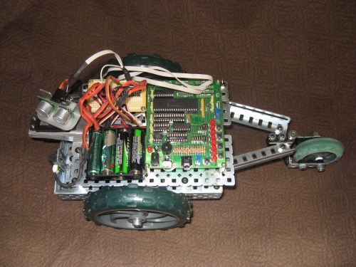
So there you go! Again, I want to give much thanks to everyone who has given me a hand on this one, from motor control and FET's to EEPROM's and all else. I will keep up with the updates as I go but for now, I have a lot of work just changing the initial MacGyvered set-up (in the video) to a proper one. Then comes the rest!
***Update 11.15.08***
Both drive systems done and installed! You would not belive the torque coming out of the wheels! Both motors are mounted with slotted holes allowing adjustment and tentioning of the drive chains. I am doing the electronic work tonight, maybe I'll have a "driving around" video tomorrow.
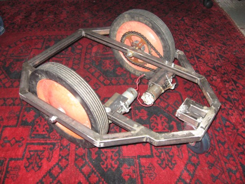
***Update 11.14.08***
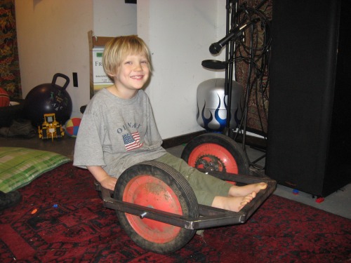
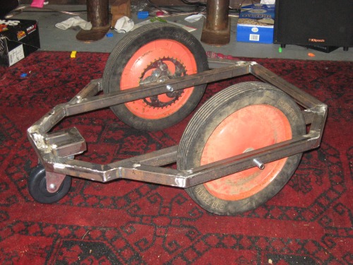
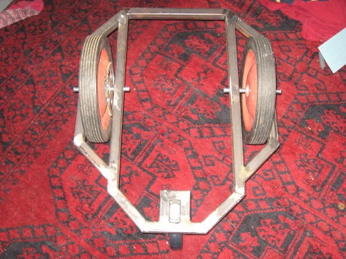
The Frame is Done!!!
(I added a picture with my boy, Charlie-Mac for an idea of scale)
***Update 11.9.08***
Huge Score, folks!!!
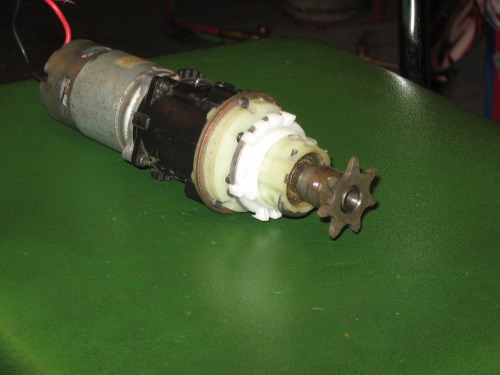
I ran into 2 old-school garage door openers and scored 2 small sprockets! Better than that, the ID was just a tiny bit smaller than the shaft comming out of my drill motor. I was able to run a tap down the middle and thread the inside of the gear to the same threading of my drill! --I also drilled and tapped 2 smaller holes for set-screws to lock it to the shaft! PERFECT!
Score number two: I found that the chain used for the garage door opener is not only 15' long, contains TWO master links but is the same pitch as a standard bicycle!!!! Off to the salvage shop. For free I scored 2 kids bikes both with 36 tooth main sprockets. I have liberated them and well, here we go:
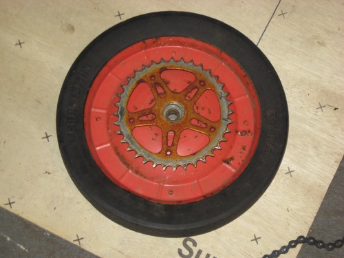
So here's what we got: 2 complete chain-drive systems, with a final gear ratio of 36:6 or 6:1. Not only is this the cleanest possible set-up I can think of but with both drills in low and another 6:1 on top of that, this thing will be able to climb a tree! --One more, I was looking at the shift mechanism on the drills... it seems quite easy and possible that a servo could be used to switch from low to high. Just think about it, the first bot here with a REAL transmission including shift-on-the-fly from "wicked fast" to "wicked torque"... OH YEAH!!
I know I should wait until I have video of this guy cruising around on the ground but I couldn't wait.
The frame is from a previous project I did and the drive method is a joke --I mean, c'mon two wheels just rubbing on eachother? The drive system on the final bot will, of course, be a belt and pulley or chain/ sprocket. For now, I am still working on the code and being sure it is "friendly" to the motor driver board. I am still suprised how sensitive these FET's can be.
As you can see on the video, I am just running a simple code of Fwd, spin right, spin left and rev. I am using the PWM code and "ramping up" and "ramping down" the speed before and after any and all changes in direction. I will have to play with it a while to see exactly what I can throw at the controller without smoking anything. For now, I have a 20A inline fuse for the main protection and I have yet to blow it. --However, I have not yet done a test with the wheels on the ground.
You can keep up with the video by watching the LED's on the board... The 2 greens are the PWM signal A/B and the reds indicate a reverse for that side.
Here's just a couple pics:
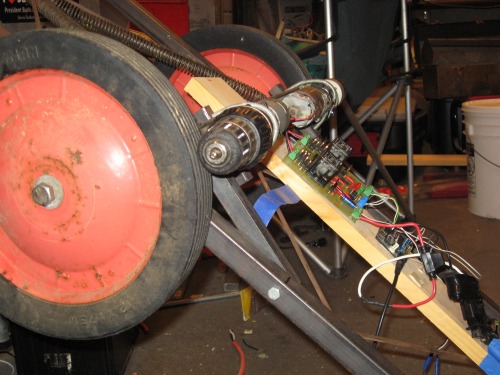
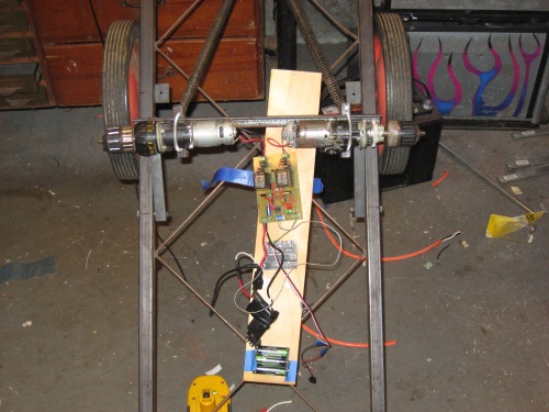
- Actuators / output devices: 2 DeWalt 12V drill motor / transmissions
- Control method: BOA's motor controller
- Power source: 14.4V DeWalt Batt. Pack
- Target environment: Anywhere!


