Help! What am I doing wrong? I have checked the connections for bogus soldering, checked the circuit plan a zillion times, checked the transistors to be sure they were in the right place, checked with a battery that the motor works and that the wiring worked in the circuit, checked to see if the recycled solar cell was giving juice.
BUT what I did not follow in the diagram is the use of just one capacitor. Are there hooked up screwy? I thought they were in parallel...and I thought that was OK. I just wanted a good strong motor response to cause the jiggling.
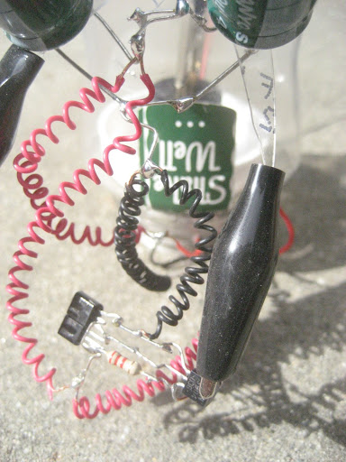
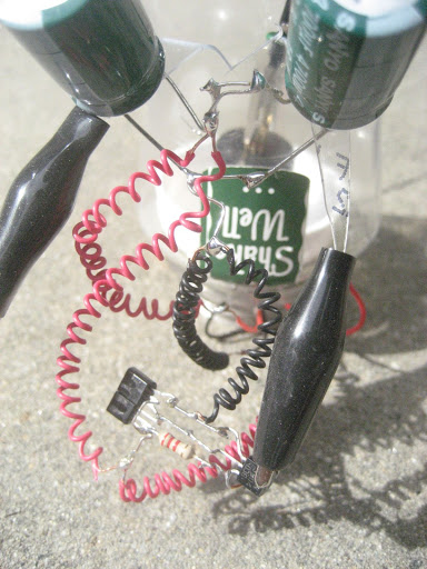
It's the easy solar engine. The circuit I redrew bigger that I am using is out in the shop...I can get it tomorrow and copy it but I am pretty sure this is it.
The original circuit, like this one, uses a single 4700uF capacitor. It looks like you used 3 4700uF capacitors in parallel. Capacitance adds in parallel, so you have triple the original value.
I haven’t done a lot of work with solar engines, but I understand they are prettty fidgety to get working. When you increase the capacitance from 4700uF to 14100uF, you are making a much longer discharge time and recharge time.
I imagine that since the goal is to jiggle, you want a faster discharge/charge time.
Did you try it with just one capacitor? If you want three caps for the look, you could use three lower value caps to try to get closer to the 4700uF value.
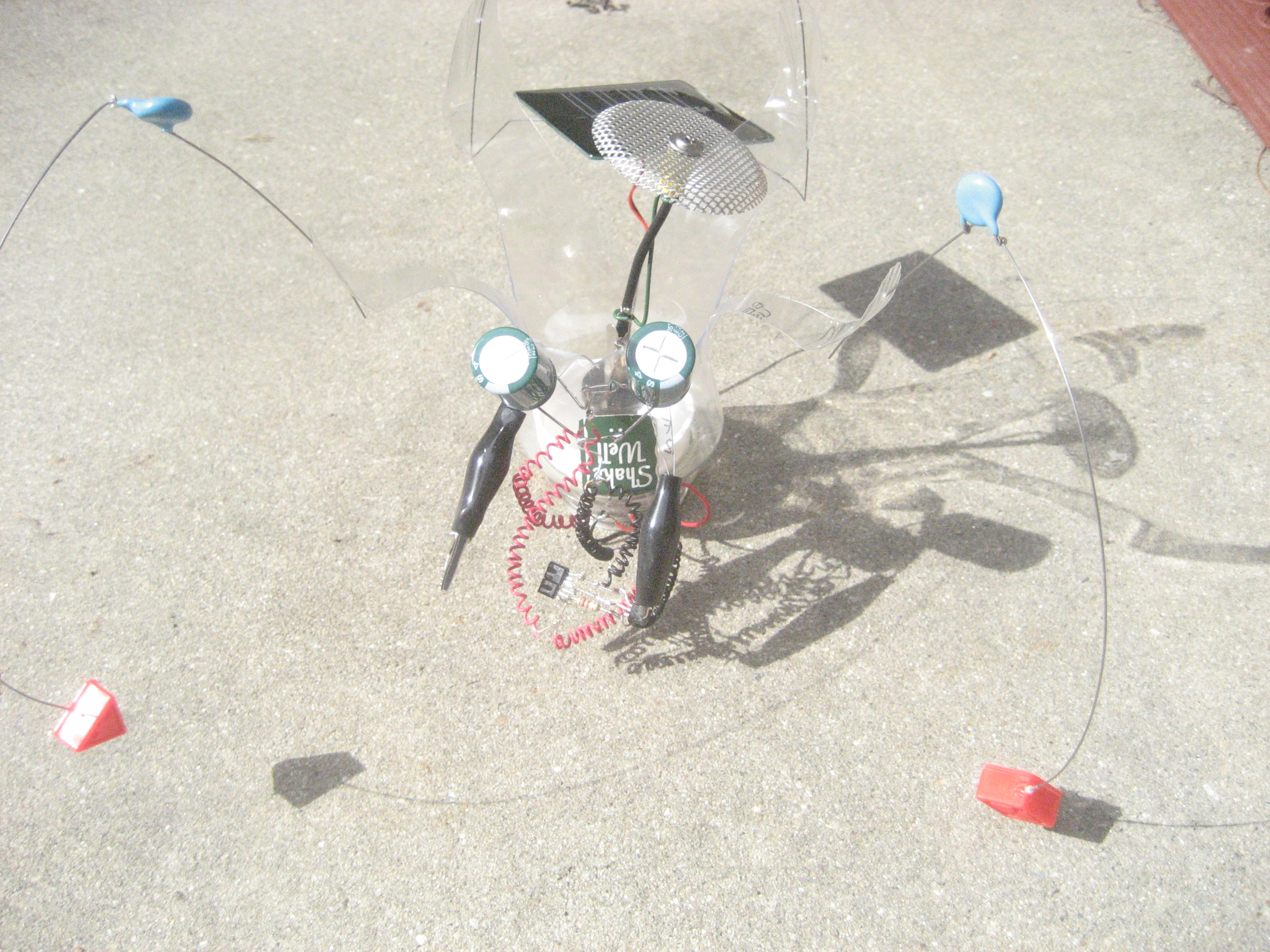
They both came off/out-of toys, Paul. The solar cell is giving me .60 of a volt under a lamp I think, and the motor spun like mad on a 1.5 v battery.
I have just two 4700uf caps in there. I figured my symet had 3 with a smaller motor (visually smaller…the short cookie tin shaped ones rather than the more motor looking motors…if that makes any sense). Anyway, I will play with the capacitors as they are the most likely variable.
How about under Good Old Sol? The 0.6V will not have a chance to trigger even a 1381C. You’ll need it to put out at least 2.0-2.5V to trigger a 1381C, IIRC. Maybe under the sun it will make enough voltage?
A 4700uF cap by itself should make a small motor with no load spin for quite awhile. With two it should twirl with reckless abandon (after ~2x the charging time)! Unless they’re toast and can’t maintain a field they are likely not the culprit.
The diodes act as the trigger. Don't use two diodes though, since you only have 0.6V to work with. If you use just one diode and put it reeeeeeeeally close to the lamp you should be able to get it to fire if all other components are nominal. Just be sure to not have a suppression capacitor across the motor terminals. I think this type of solar engine gets weird oscillations if you do.
I thought the solar cell (which, BTW, did no better out in the sunshine) trickled juice into the caps…like a dripping hose into a bucket. When the caps were charged enough their potential triggered the 1381…so if I wasn’t in a hurry any trickle charge would work. Sort of right?
The glory of a solar engine is it can accumulate more current than the solar cell alone can generate and thus can do many more things (albeit in short bursts) than the cell by itself. The overall voltage is limited by the solar cell, which is what triggers the engine to fire. As the cap fills with electricity the voltage slowly climbs, hopefully past the trigger setpoint. Your circuit voltage will only go as high as the solar cell, sorry.
I agree. If the solar I agree. If the solar panel is only generating 0.6v in sunlight, that’s the problem. Like JAX says, the caps will accumulate the 0.6v trickle all day long into the bucket, but at the end of that day, it will still be a bucket full of 0.6v. Extra food for thought: a solar panel in the shade or darkness will drain your caps or a battery since it will read 0v and volts will flow in reverse from battery or caps to solar panel. So depending on the the project, solar panel circuits should have a diode to prevent reverse flow. But, like an LED, diodes will cost your another 1.6v volt to operate. for example, if your solar panel generates 6v and you put a diode in series, you will yield 4.4v downstream.
Great point, Paul. Many small solar panels I have seen already have a small diode installed on one of the contacts. If your new panel does not have one, you should consider adding one.
I think the forward voltage drop across the typical silicon diode will be more like 0.7V, though.
ok thanks, that sounds right. I knew something didnt feel right as I was typing that. I’m getting rusty. I need to get back into this stuff more.
I have some of those tiny panels that Emma is using here, and at first they work great, then they begin to erode around the edges and you can see bubbles from seperation begin to form, which ruins they’re performance. they should come with a warning label "DO NOT EXPOSE TO DIRECT SUNLIGHT"
Emma, are you also noticing that type of erosion on the solar panel? thats probably why its only generating 0.6v


 **
**