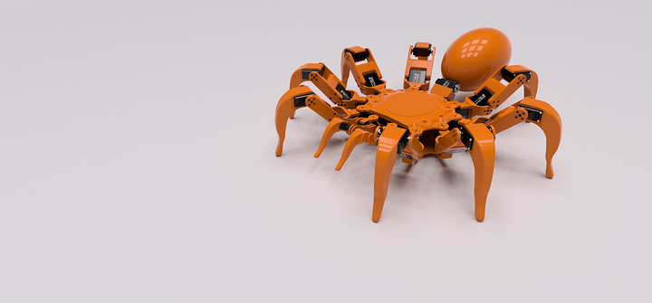
Artus-X TARANTULA Robot

I thought i should share my latest work in progress.

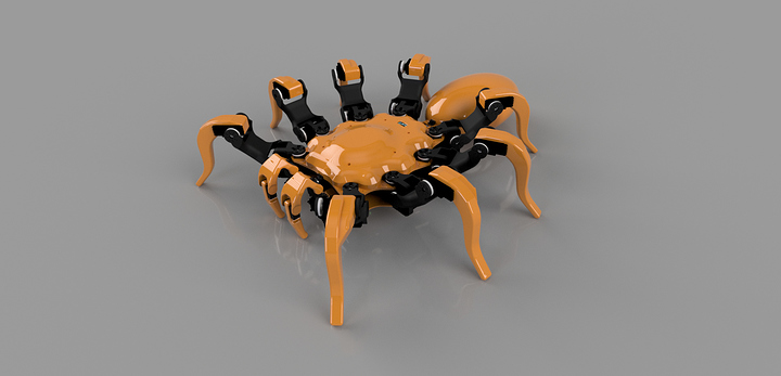
This is the Artus-X. Artus-X comes from the Latin translation of Ten Limbs
The A.r.t.u.s-X or Articulated Robotic Tarantula Universal Simulation 10

A tarantula has four pairs of legs and two additional pairs of appendages. Each leg has seven segments, which from the prosoma out, are: coxa, trochanter, femur, patella, tibia, tarsus and pretarsus.
In this article we will only be looking at the coxa, femur, tibia, tarsus/pretarsus as well as the fifth pair.

The fifth pair are the pedipalps, which aid in feeling, gripping prey.
The sixth pair of appendages (Not realised here)are the chelicerae and their attached fangs.

The tarantula leg oscillations are more loosely coupled to each other. The two sides
may maintain different rhythms. The pedipalps and even first legs may be slower than
the rest.

When walking, a tarantula’s first and third leg on one side move at the same time as the second and fourth legs on the other side of its body. The limb movements of many multilegged animals occur in metachronal sequences, often sequences running from posterior to anterior. Such sequences are not so conspicuous in animals with few legs. However, for the walking of certain insects with variable gaits it has been possible to produce a descriptive model based on metachronal rhythms with stepping pattern varying with frequency.

For simplicity
one can assume that legs on opposite sides of the animal always alternate and then make the following formulation for legs of one side. Number the legs 1, 2, 3, and 4, from front to back. Then the basic stepping sequence in the model is 4321. Again for simplicity, hold the interval between 4 and 3, 3 and 2, and 2 and 1 constant. Vary the repetition rate of the whole set.

The stepping sequences of these spiders are in fact fairly similar to those of most insects. Aside from the difference in number of legs, however, there is another significant difference. The legs do not necessarily step at exactly the same frequency so there are sometimes phase drifts between given legs even during steady locomotion. At first sight the majority of the observations do appear to fit the model, but with rather a lot of random variation.

At present the robot will have 24 HS705bb quarter scale servos for its 8 3dof limbs along with to other appendages called pedipalps. These will consist of 4dof each.

Running the famous phoenix code i have added the additional appendages and a couple of other features including a 2dof abdomen.
The code has been ported over to the Arduino Mega 2560 and also uses the SSC32-U servo board. At the moment i have it coded for the PS2 but later i would like to move it to RC.

I am currently in the production stage so i should soon have some assembly to show you.
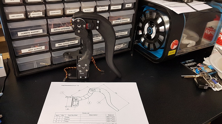
A test leg has been printed at 15% infill as a prototype but i will be printing the legs and body at 50-75%.

Everything has been designed in fusion 360 and 3d printed on a Stratasys F170 3D Printer in ASA.

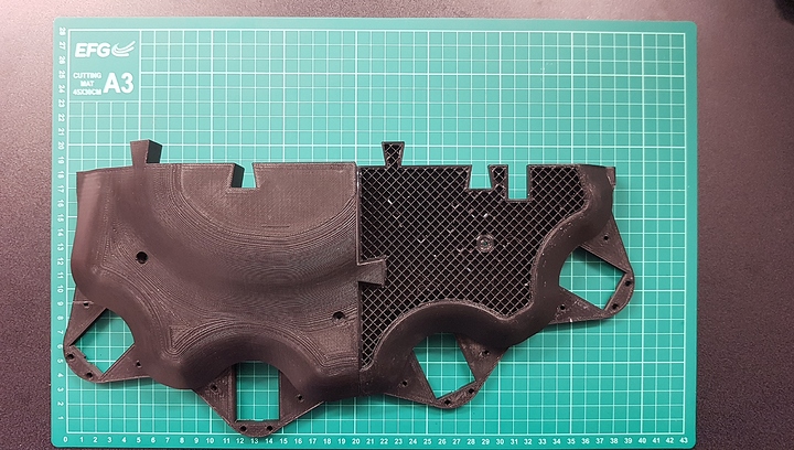
The body plate, along with the leg sections are rather large and so the body top plate has been printed in 4 parts and uses dove tail joints to lock it together.
So far the body has taken a total of 36 hours to print. Only one half shown here.

As soon as i have more to show i will.

Questions welcome.

3 Likes

Nice work. looks really good. it’s a pretty ambitious project!

Thanks. Possibly ambitious but not far from my daily challenges. Looking forward to getting this assembled. Just waiting for more filament.

Stunned again innerbreed… How will you power it ?

Amazing work as always. How do you create your walking gait / inverse kinematics?

The internal has lots of room for peripherals power supply so I am not really limited when it comes to space. I plan two Turnigy 5000mAh 3S 40C Lipo Packs wired in parallel to give me 11.1v at 10A that I can step down to 6v to power the servos and ill used a couple of 9v for the boards.
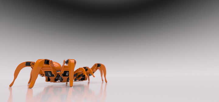
Towards the back of the robot (rendered image) you can see a small LCD. This will show battery levels as well as the current Gait being used.
I have developed 4 gaits at the moment. Tarantula, Scorpion, Lobster, a Quad-rippleWave and then a test gait where I am currently making changes to it and observing it for gait improvements in the future.

Thanks. It’s currently running on a phoenix based code but I have added the other appendages to the IK.

I have added CPR (centre point of rotation) to the code so we can change the body’s axis of rotation along the Z axis meaning we can have a more playful movement when doing rotations.
I am currently working on a Terrain Adaption part as well as implementing a MPU6050 so we can detect external movements so we can keep the body level. (just a bit of fun)

Along with this i have also added the movements for the fifth pair (pedipalps) on Right J/Stick. This will allow us to control the tilt angle in and out when walking as well as when Translating. The Pedipalps have been added into the gait engine also.

So with regards the the Gait engine i have developed a few gaits. some experimental until i have fully tested them.

if (GaitType == 0) {    display.println (" TARANTULA");   
//            Left                  Right      
    GaitLegNr[cLP] = 1;    GaitLegNr[cRP] = 8;
    GaitLegNr[cLF] = 8;    GaitLegNr[cRF] = 4;  
    GaitLegNr[cLMF]= 5;    GaitLegNr[cRMF]= 1; 
    GaitLegNr[cLM] = 3;    GaitLegNr[cRM] = 7;
    GaitLegNr[cLR] = 6;    GaitLegNr[cRR] = 2; 
    
         NrLiftedPos    = 3;
         HalfLiftHeigth = 0;
         TLDivFactor    = 6;      
         StepsInGait    = 16;    
         NomGaitSpeed   = 75;            
}
//----------------

if (GaitType == 1) {    display.println (" SCORPION");    
//            Left                  Right      
    GaitLegNr[cLP] = 0;    GaitLegNr[cRP] = 0; 
    GaitLegNr[cLF] = 4;    GaitLegNr[cRF] = 8;  
    GaitLegNr[cLMF]= 7;    GaitLegNr[cRMF]= 3; 
    GaitLegNr[cLM] = 2;    GaitLegNr[cRM] = 6;
    GaitLegNr[cLR] = 5;    GaitLegNr[cRR] = 1; 

         NrLiftedPos    = 3;
         HalfLiftHeigth = 0;
         TLDivFactor    = 4;      
         StepsInGait    = 16;    
         NomGaitSpeed   = 90;       
}
//----------------
  
if (GaitType == 2) {      display.println (" TICK");  
//            Left                  Right
    GaitLegNr[cLP] = 0;   GaitLegNr[cRP] = 0;
    GaitLegNr[cLF] = 6;   GaitLegNr[cRF] = 2;
    GaitLegNr[cLMF]= 4;   GaitLegNr[cRMF]= 8;
    GaitLegNr[cLM] = 3;   GaitLegNr[cRM] = 7;
    GaitLegNr[cLR] = 1;   GaitLegNr[cRR] = 5;

         NrLiftedPos    = 1;  
         HalfLiftHeigth = 0; 
         TLDivFactor    = 5; 
         StepsInGait    = 8;  
         NomGaitSpeed   = 100;
}
//----------------

if (GaitType == 3) {     display.println (" LOBSTER"); 
//            Left                  Right      
    GaitLegNr[cLP] = 0;   GaitLegNr[cRP] = 0;
    GaitLegNr[cLF] = 3;   GaitLegNr[cRF] = 1;        
    GaitLegNr[cLMF]= 6;   GaitLegNr[cRMF]= 5;     
    GaitLegNr[cLM] = 1;   GaitLegNr[cRM] = 3;
    GaitLegNr[cLR] = 5;   GaitLegNr[cRR] = 6; 

         NrLiftedPos    = 2;
         HalfLiftHeigth = 0;
         TLDivFactor    = 16;      
         StepsInGait    = 18;        
         NomGaitSpeed   = 85;
}
//----------------

if (GaitType == 4) {     display.println ("TRIPPLER"); 
//            Left                  Right      
    GaitLegNr[cLP] = 4;   GaitLegNr[cRP] = 4;
    GaitLegNr[cLF] = 3;   GaitLegNr[cRF] = 1;        
    GaitLegNr[cLMF]= 2;   GaitLegNr[cRMF]= 2;     
    GaitLegNr[cLM] = 1;   GaitLegNr[cRM] = 1;
    GaitLegNr[cLR] = 2;   GaitLegNr[cRR] = 3; 

         NrLiftedPos    = 2;
         HalfLiftHeigth = 1;
         TLDivFactor    = 3;      
         StepsInGait    = 12;        
         NomGaitSpeed   = 85;
}
//----------------

if (GaitType == 5) {     display.println ("TARANTULA2");     
int LPPedistep =random (4, 8); 
int RPPedistep =random (20, 24);
//            Left                           Right      
    GaitLegNr[cLP] = LPPedistep;    GaitLegNr[cRP] = RPPedistep;
    GaitLegNr[cLF] = 28;            GaitLegNr[cRF] = 12;  
    GaitLegNr[cLMF]= 16;            GaitLegNr[cRMF]= 0; 
    GaitLegNr[cLM] = 8;             GaitLegNr[cRM] = 24;
    GaitLegNr[cLR] = 20;            GaitLegNr[cRR] = 4; 

         NrLiftedPos    = 3;           
         HalfLiftHeigth = 0;
         TLDivFactor    = 6;      
         StepsInGait    = 32;    
         NomGaitSpeed   = 75; 

With regards the to last one "“Tarantula2” i have added the Pedipalps on a random number selection since these do not appear to have a set pattern unlike the rest of the legs. Not sure if that will do as i expect and again the code is totally untested but i feel it is the most accurate to real life. The sequence runs in this order;

 RMF,             RR, LP,          LM,            RF,            LMF,             LR, RP,         RM,             LF,                                
   0,  1,  2,  3,  4,  5,  6,  7,  8,  9, 10, 11, 12, 13, 14, 15, 16, 17, 18, 19, 20, 21, 22, 23, 24, 25, 26, 27, 28, 29, 30, 31

The LP and RP are the Left and Right Pedipalps.
These are set to jump into play at random placements between the movements of the RR - LM (placements 4-8 ) for the Left Pedi and LR - RM (placements 20-24) for the right pedi directly within the gait engine. So no two steps the same. :wink: But again… untested at this point.
Below is the repository that i have added the full code too and this will be updated as i go and if anyone has any input or sees something that just simply wont work please let me know. As always when i post code i want to thank the people involved and so apart from the main contributors Xan. Zenta and Kurte i also thank the rest of the community back from years ago when we all watch this develop into what it is today.

Having recently lost my job (right before Christmas too) i have done a couple of other iterations of for the project to help cut cost. In doing so this have obviously changed the scale spec for the tarantula.
Going with a RDS-3115MG servo package and scaling it down has had its challenge and so i completely redesigned the project.

The design will be much more compact as you can imagine. It is now almost half the size however still a beast. The redesign has gone through several stages while i was modelling different servos. I even went Micro at one point. looked cute but was not practical and possibly wouldn’t have worked as well.

So until i have the funds to push this project into the next stage of developing ill throw in a couple of these renders for now.

Let me know your thoughts.

Again, as i was already aware, sorry to hear about your job.
I think in the end they will loose more than you.

I’m usually not too critic but …

  • I like the femur of the original one. More style to it
  • Is there a reason why you move from stationarry center body servo to moving ones ? Space ?

:slight_smile:

yes the femur is a little too blocky on this one and is something i did have in mind to change so i am happy you mentioned that.

Centre body servo?

Do you refer to the CPR Centre Point of Rotation i mentioned before?

The original version had the servos integrated in the frame body.
Maybe the servos do not fit the smaller frame now ?

i see. yeah i have reversed them so they are fitted the same way as the phoenix hexapods are with the coxa attaching to the centre plate and not the servo body, so that there is more room inside the body.
Here is an idea for an improved Femur?

Yes, much better

1 Like

So i have been looking into the idea of integrating a Pixy2 camera for image recognition and reactive responses to external stimuli.
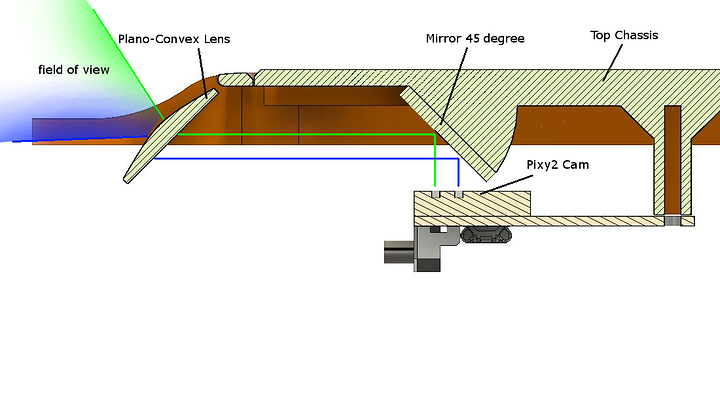
The Pixy2 is a lot smaller than the first Pixy however it is still too large especially since i would like the final look to not have peripherals sticking out all over the place so i have opted to integrate the camera inside of the body and have the field of view convex through the top chassis via a mirror at 45 degrees and a convex lens to allow for a larger field of view.

I am not too sure whether the set up is correct and if the convex lens will actually give me a wider view?
I have mounted the camera so that when the image bounces off the mirror the final image will be the correct way up but i am now thinking that the lens will conflict with this and re-flip it?

perhaps use a convex mirror instead. Here in the US they sell sticky back mirrors to attach to the side mirrors of older cars to give a wider field of view. They are found at auto parts places and cost a couple dollars or so.

My thought processes are cloudy today, but I do think the lens will “flip” the image. In addition, I suspect you will have problems with focusing – the lens will need to focus at one point and the camera lens will need to focus on the same point. Well, more or less. There are ways around that but optics isn’t my strong point.

Focus. yes that didnt cross my mind and i believe you are correct there. I like the idea of the convex mirror or similar as that would solve the focus problem. What i may do is see if i can de-solder the actual lens part and re-solder with wires then mount that to the body, keeping the board inside.

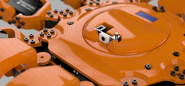
i have opted to place the camera slightly poking from the top. keep it simple it guess.
That top panel is removable to allow serviing on of the SSC32 and Battery compartments.
Simply slides off from around the camera. Note the small LCD for battery monitor and notifications on function.

What a beauty!!
I will definitely be following this

1 Like

Am i seeing an optional turret version ?