

mechDOG Kinematics, Trajectory, Synchronization & Gaits

- Inverse Kinematics
- Static & Dynamic Gaits
- Stability & Balancing
- Foot Trajectory & Walking Synchronization
How does the Inverse Kinematics code work?
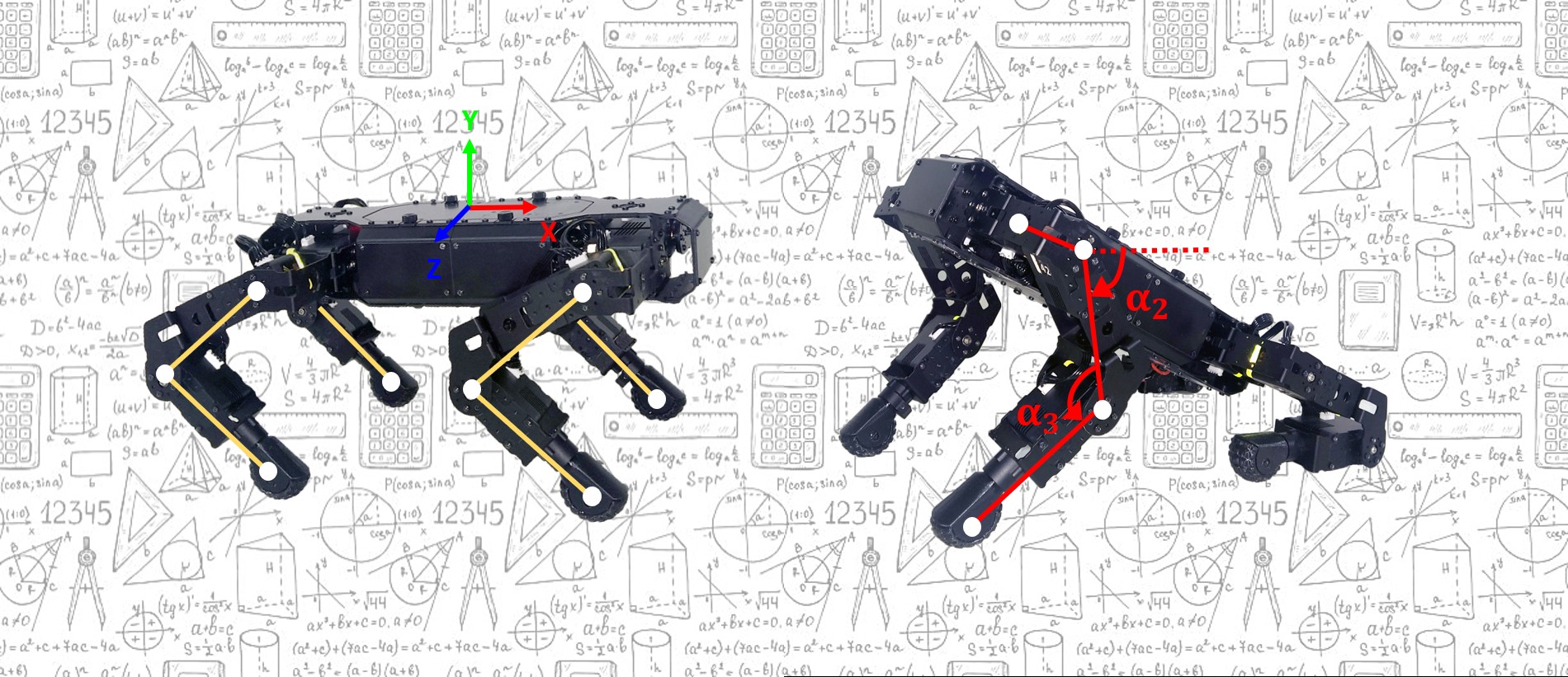
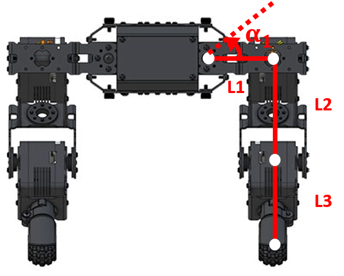
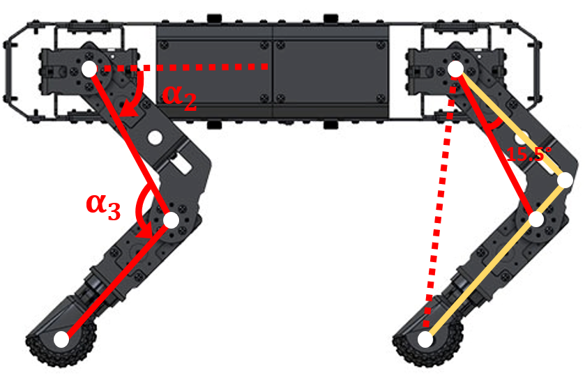
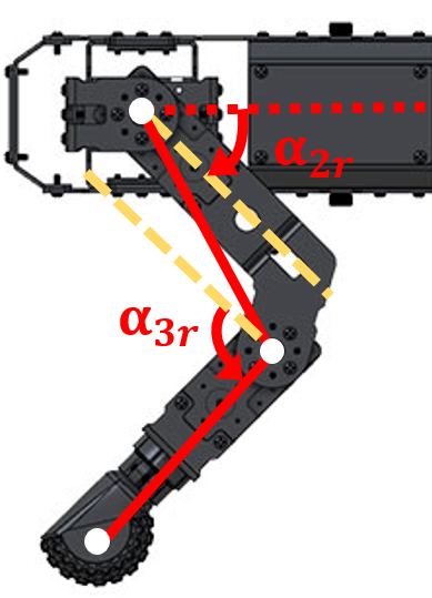
Inverse Kinematics involves calculating the joint angles needed to move the legs to a specific position, this can be achieved by using a geometrical analysis. The following figures show the front and side view of the legs where the red lines mark the triangles formed by the joints, these were used as the basis for the IK calculations, and the yellow lines are there as a reference to mark the offsets that need to be taken into account to get the final angles.
The following figures show the triangles formed by the joints if the legs were to move along the Z and X axis.
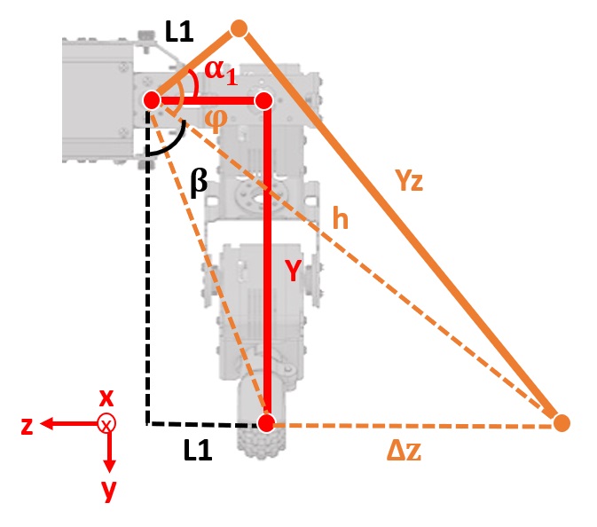
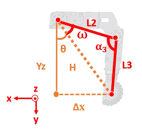
By using trigonometry we are able to write the following equations:
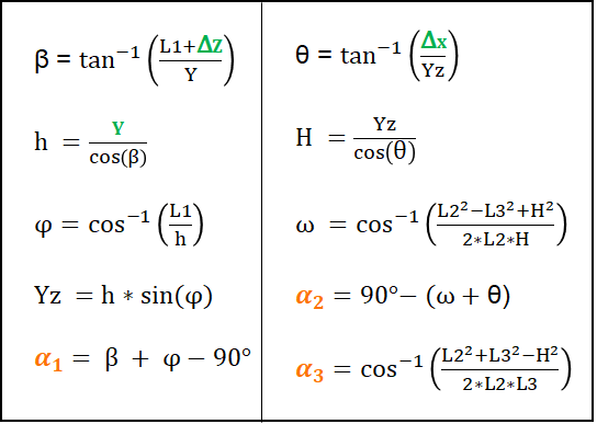
* The variables in green are inputs and the orange ones are the output angles.
Note that the angle for joint two (𝝰2) isn’t ⍵+𝚹 but 90°-(⍵+𝚹), the reason for this is that the origin for the angle in the ideal model isn’t the same as the origin for the servo in the real robot.
Nevertheless, those aren’t the final equations as we still need to consider the offsets between our ideal model and the real model.
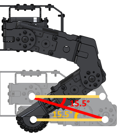
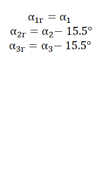
Once all the offsets have been taken into account we have the final angles that need to be sent to the servos to move the feet to a specific location. However, this alone will not allow mechDOG to walk; for this, we will need to synchronize the motion between the legs and include some additional factors.
Static vs Dynamic Gait
A quadruped robot might walk best on complex terrain using a statically stable gait or walk quickly using a dynamic on flat terrain.
A static gait is the one where the quadruped robot maintains stability during the entire motion, which keeps the center of gravity of the robot inside a supporting triangle composed of the three feet which are in contact with the ground and each leg of the robot is lifted up and down sequentially.
Dynamic gaits are often used to run and trot because of their efficiency. For this gait, two diagonal legs are lifted at the same time, and the other two legs are in contact with the ground until the moving legs land on the ground. The four legs of the quadruped robot repeat the motion two by two.
Insights from a development perspective
Stability & Balancing
For a quadruped to be stable when walking, the vertical projection of the center of mass should be located inside the supporting virtual triangle created by the three feet on the ground.
While using a static gait the center of gravity of the robot shifts to the opposite side of the leg that is being lifted, so depending on the weight distribution of the robot this may cause it to lose stability. In addition, the inertia generated by the acceleration of the lifted leg may also contribute to the instability. For mechDOG, this was the case, which is why we opted to add a balancing sequence to compensate or counterbalance the motion while walking using the static gait.
How does the balance sequence work?
To maintain the center of mass within the stability triangle during the static gait, a horizontal oscillation synchronized with the sequence of movement of each leg was implemented. First, a linear function was used to establish the oscillation of the center of mass, this was later changed to a sine function to keep the robot at the extremes as long as possible and to improve the smoothness of the motion.
It should be noted that the balancing function is only necessary for the static gait because the symmetry of the motion in the dynamic gait helps maintain the center of mass aligned on the axis of symmetry and thus avoid unbalance.
Foot trajectory & Walking synchronization
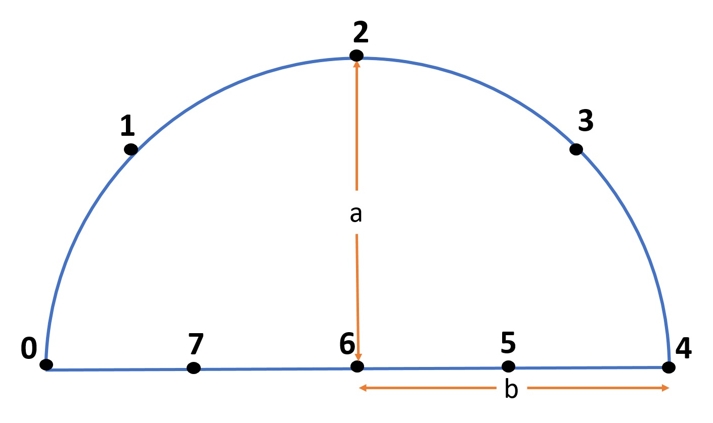
The movement of each leg is periodic and follows a semicircle in a 3D plane, this trajectory is discretized, taking 4 fixed points for the segment of the trajectory in the air. Each displacement from one point of the trajectory to the next is executed every N milliseconds, therefore, as N varies, so does the speed of the gait.
With more samples of the trajectory, the motion approximates more closely to a circle, however, the motion would be slower due to the time required to calculate the inverse kinematics for each point, which is limited by the computational capacity of the motion controller.
The type of gait is determined by the offset between each leg and the ratio of the time in the air to the time on the ground.
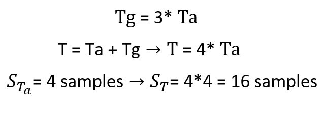
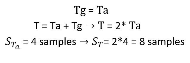
For the static gait the offset between each leg should be 90 degrees, and to ensure that there are always 3 feet in contact with the ground, the contact time should be 3 times the time in the air.
To implement this, we chose to vary the number of samples in a cycle, obtaining for the static gait:
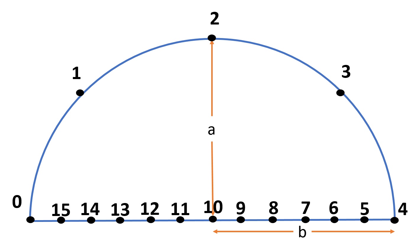
For the dynamic gait, the time in the air is the same as on the ground and the legs are 180 degrees out of phase, so there will be two legs synchronized at the same point of the trajectory, for example at point 0 and two others 180 degrees for example at point 4 of the trajectory.
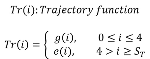
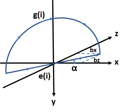
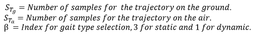
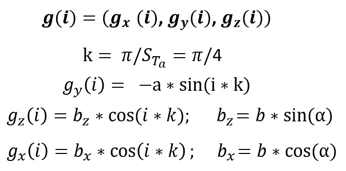
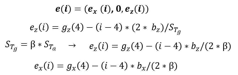
The following is a general description of the principle used to calculate the points of the trajectory and the synchronization of the legs, for this purpose the motion cycle was divided into two functions: e(i) and g(i), where i is the sample number of the complete cycle and is used to calculate the XYZ position of the foot for a gait of height a and step length 2b, with a direction of α.
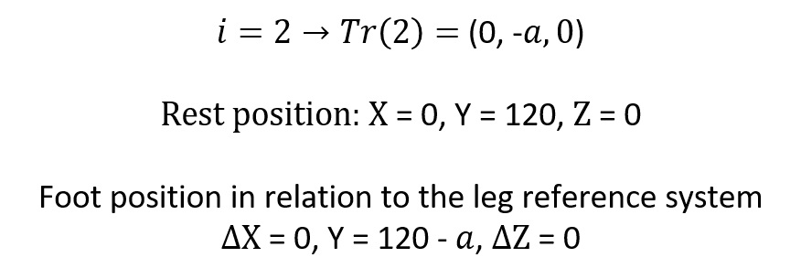
After having the inverse kinematics of each leg and the desired points of the trajectory in the XYZ plane we can perform a controlled movement of the foot. The coordinates of the trajectory of the foot have their origin in the center of the circle, these coordinates (0,0,0) represent the rest position of the robot, in which the feet must be when the robot is not walking. Thus the final position of the foot must be the sum of the position of the foot with respect to the origin of the coordinate system of the trajectory plus the distance between this origin and the articulation 2 of the leg, in other words, plus the distance between the references of the two coordinate systems.
For example, to keep the robot at a height of 120mm while walking, the foot coordinates used as input for the inverse kinematics would be as follows:
The gait implemented is based on a periodic motion, the four legs perform the same synchronized movement. As already mentioned, to select the type of gait it is necessary to adjust the ratio between the displacement time in the air and on the ground and to add in each leg an offset of 90 degrees for the static gait and 180 degrees for the dynamic gait.
To synchronize the movement of each leg, an offset was added to the argument of the trajectory function. For dynamic gait, an offset of 180 degrees equivalent to half a cycle of motion is required, for example, if the period has 8 samples, each one must have an offset of 4 samples. While in static gait the legs must be 90 degrees out of phase, which represents a quarter of the movement, because the period has 16 samples the offset would also be 4.
Thus we would have that the position of each leg at the same instant would be given by:
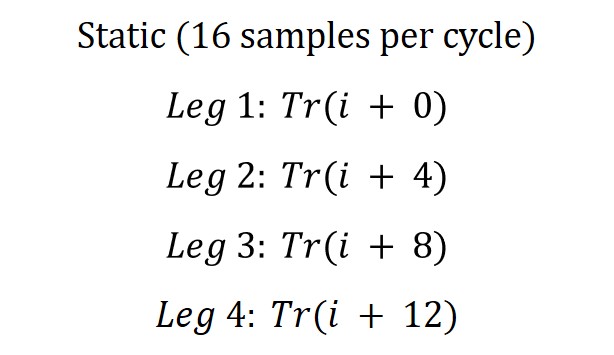
Where i varies from 0 to 15. This cyclic counter (i) is simple to implement using the modulo operator % with respect to the period of the movement.
In the case of dynamic gait (8 samples per cycle), i varies from 0 to 7.
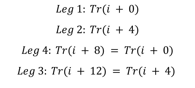
Note that for this case the order of the sequence (leg ID) changed to correctly synchronize the gait.
Have any questions, spot any issues or want to continue the discussion? Write in the comments section below.
Thanks for helping to keep our community civil!
This post is an advertisement, or vandalism. It is not useful or relevant to the current topic.
You flagged this as spam. Undo flag.Flag Post
Your post is currently under review by our moderation team. The review process usually takes up to 48 business hours.
You can track your post's status in the "My Content" section of your profile. Once approved, it will be published and visible to others.

Thank you for contributing to our community!