

Cytron Design: DC Motor Driver - How it works

I worked for Cytron Technologies which is famous for its wide range of brushed DC motor drivers with high performance at affordable price. I started to design motor driver since year 2010 and the MD10C R1 was my first motor driver with full NMOS H-bridge design.
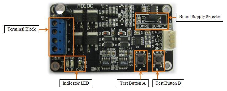
The very early version of MD10C
This version was less than perfect and had gone through several revision. The MD10C in the market today is Rev. 3 and it's one of our best selling motor drivers.
As the core designer for all the motor drivers, I'll be sharing bits & bytes and what I've learn and applied in our motor driver design throughout the years.
Before this, I've talked about Fundamental of PWM Speed Control for Brushed DC Motor in another post. Now let's move on to something more advance and look at some concepts and theories behind the Brushed DC Motor Driver.
Electrical Model for Brushed DC Motor
Since we're going to design a motor driver, it's useful to know the electrical model and characteristic of a Brushed DC Motor.
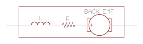
Electrical model of brushed DC motor.
Basically a DC motor is modeled as 3 components internally:
- Inductance (L) of motor armature winding.
- Resistance (R) of motor armature winding.
- Back Electromotive Force (Back-EMF) - DC motor can also act as a generator. The Back-EMF is the voltage generated by the motor when rotating. The value is proportional to the rotating speed but opposing the supply voltage. The higher the rpm, the higher the Back-EMF voltage and vice-versa.
According to Ohm's Law, Current (I) = Voltage (V) / Resistance (R).
Thus for DC motor,
Motor Current = (Battery Voltage - Back-EMF Voltage) / Winding Resistance
Example:
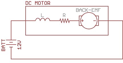
Motor is connected to a battery
Battery is connected to the motor terminal when the motor is standstill.
Because of the motor is not rotating, the Back-EMF is 0V. Motor current will max out and is only limited by the motor winding resistance. This is also the stalled current of the motor and it can be much more higher than the rated current. Please take note that using the motor over the rated current/torque for excessive time will fry the motor.
Motor Stalled Current = Battery Voltage / Winding Resistance
The motor torque is proportional with the motor current, thus a motor will produce maximum torque when stalled or during startup.
If the torque is high enough, the motor will accelerate and the speed will increase. At the same time, motor Back-EMF voltage will increase too and causing the motor current to decrease (because the Back-EMF voltage is opposing the battery voltage). The motor will accelerate to a point where the motor current is just enough to drive the load of the motor and stabilize.
If there isn't any load connected to the motor shaft, the motor will just accelerate to the motor's "No Load Speed". At this speed, the Back-EMF voltage is just slightly below the battery voltage. Motor current is minimum (No Load Current) and the torque is just enough to overcome the mechanical friction to keep the motor running.
Motor Braking:
If a motor is running and we disconnect the battery, the motor becomes generator and the voltage across is dependent on the speed. Without any external force, the motor will just coast to stop due to the mechanical friction.
What happen if we connect and short both motor terminal together? Current will start to flow in the opposite direction due to the Back-EMF of the motor. This negative current will produce torque opposing the motor direction causing the motor to slow down and effectively brake the motor.
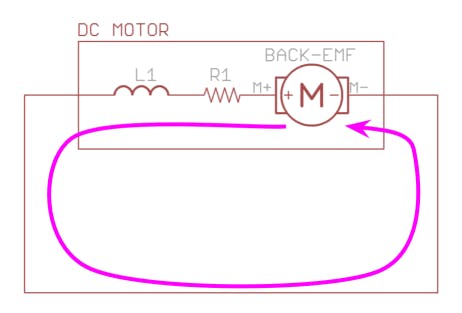
Current path during motor braking.
Motor is coasting to stop.
Motor is braking
OK, I think we have enough theory for Brushed DC Motor. Let's move on to the motor driver.
Basic Uni-Directional Motor Driver
We start with something simple first. This is the schematic for a very basic uni-directional motor driver which can only drive a motor in 1 direction.
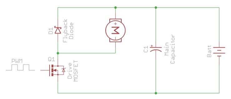
Schematic of basic uni-directional motor driver
Still remember a motor electrical model consists of 3 components: resistance, inductance and Back-EMF? We talked about the resistance and Back-EMF but not the inductance. Now we will explore more on the winding inductance as it plays an important role when designing a motor driver with PWM speed control.
According to All About Circuits, the equation for inductor is as follow:
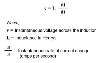
The property of inductance prevents it's current to change instantaneously. Instead, the current will rise or decrease slowly and the rate is dependent on the applied voltage and inductance value (di/dt = V/L).
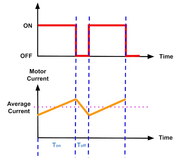
From the graph, we can see that the motor current rises slowly instead of jump to the max immediately when the MOSFET is on.
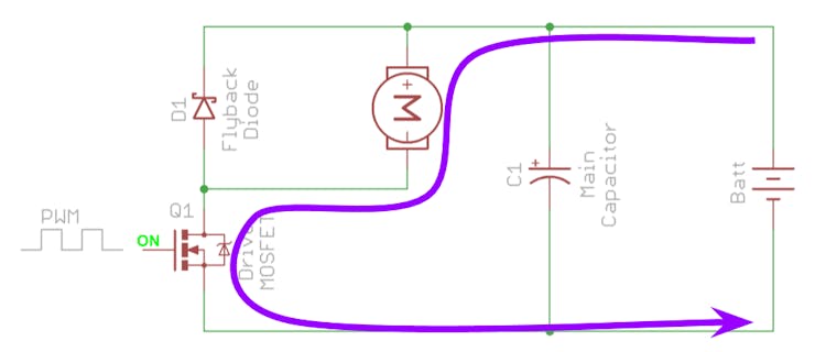
Current path when the MOSFET is on
Flyback Diode:
Same thing happens when the MOSFET is turned off, the motor current cannot decrease to 0 immediately. This is where the Flyback Diode D1 comes into play. It provides an alternative path for the motor current to flow when the MOSFET is turned off.
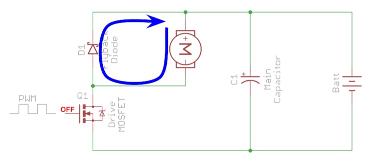
Current path when the MOSFET is off
Without the flyback diode, the motor current is interrupted and has nowhere to go (di/dt is negative and very high). This will cause a voltage spike across MOSFET Q1. Usually this voltage can be a lot higher than the motor voltage and it may damage the MOSFET if over its maximum rating.
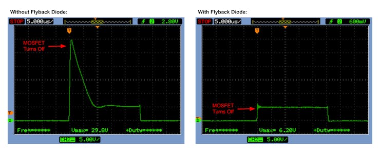
Voltage across MOSFET when turning off
We connected a shunt resistor in series with the motor and probe the voltage difference with a oscilloscope to measure the motor current and this is what we get.
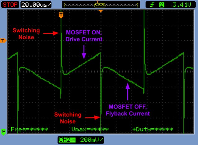
Motor Current when driven with PWM signal
You can see that whenever the MOSFET is switching, there will some switching noise. This is because in the real world, the flyback diode is not ideal. It takes some time to start conducting when switching from reversed biased (when MOSFET is on) to forward biased (when MOSFET is off) and vice versa. That's why it's recommended to choose a Schottky diode with fast recovery time to minimize the switching noise.
Main Capacitor:
Another critical component in a motor driver is the main capacitor but it is often overlooked. It's especially important if you have a very long wires from the battery to the motor driver.
When the MOSFET turns off, it not only chops off the motor current. In fact, the current flowing from the battery will be interrupted too. Battery and wires do have some inductance and if its current is interrupted, there will be voltage spike. Thus a main capacitor with generous capacitance is needed to absorb the inductance current and reduce the voltage spike.
When the MOSFET turns on again, current will be drawn from the battery. Again, battery and wires inductance prevent the current to flow quickly. The main capacitor will supply this current and prevent the voltage drop during this period until the current from the battery start flowing.
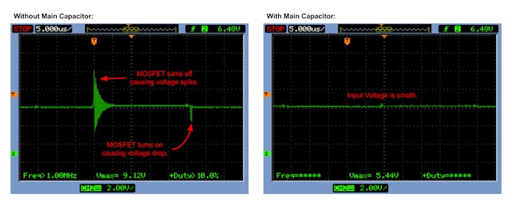
Input Voltage during MOSFET switching
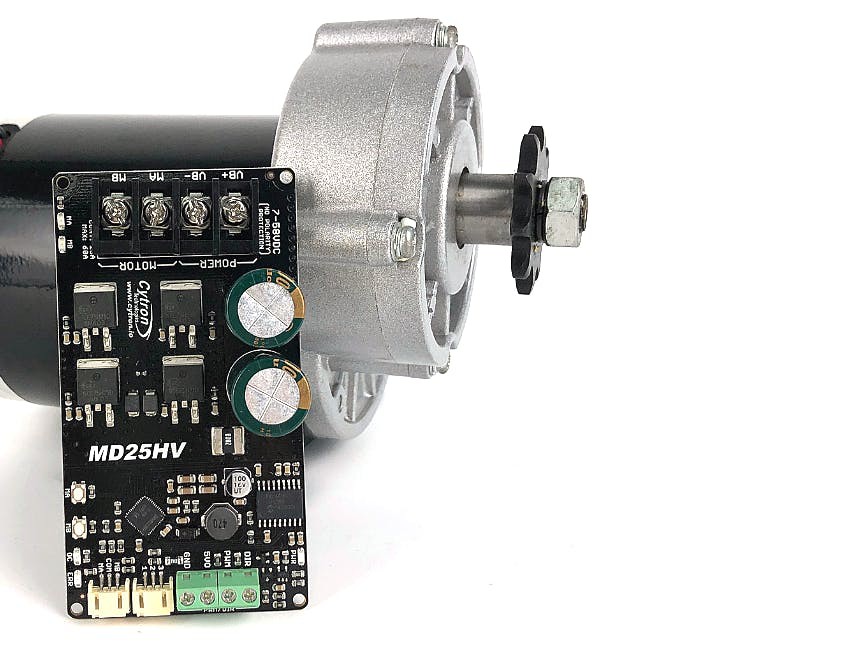
Because of this, Cytron's motor drivers are always fitted with large main capacitor.
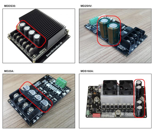
Main Capacitors on Cytron's motor drivers
In actual application, MOSFET is switched at high frequency and the main capacitor will be working very hard. Don't be surprised if the main capacitor has temperature as high as the MOSFET.
Battery Current vs Motor Current:
One fact about motor driver which is not so commonly understood is that under PWM drive, the battery current is not the same as motor current. Battery current only flows when the MOSFET is on. If the MOSFET is driven with PWM at 50% duty cycle, battery current only flows for 50% of the time and the average battery current will be half of the motor current. On the other hand, the voltage "seen" by the motor is only 50% of the battery voltage.
Of course this is ideal case. In reality, battery current will be slightly higher than 50% of the motor current due to the power lost in the motor driver.
Hence, if you want to measure the actual motor current, put the current sensor / Amp meter in series with the motor. Do not put it in series with the battery / power supply.
Uni-Directional Motor Driver with Synchronous Rectification
Synchronous rectification is a technique of improving the efficiency by replacing the flyback diode with a MOSFET. As explained earlier, the purpose of the flyback diode in a motor driver is to conduct the motor flyback current (due to inductance) when the MOSFET switches off. However, diodes do have a voltage drop of around 0.5V - 1V resulting in some power lost in the diode during the flyback phase. Remember? Power (P) = Voltage (V) x Current (I).

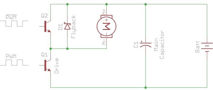
Schematic of uni-directional motor driver with synchronous rectification.
One interesting fact about MOSFET is that, when the MOSFET is turned on, it conducts current in either direction.
In this circuit, Drive MOSFET Q1 switches on during the driving phase and Flyback MOSFET Q2 switches on during the flyback phase. This way, the power lost is minimum and only dependent on the MOSFET internal resistance (Rds On). This is much more lesser compared to the power lost of the diode.
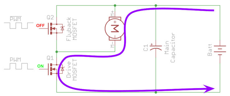
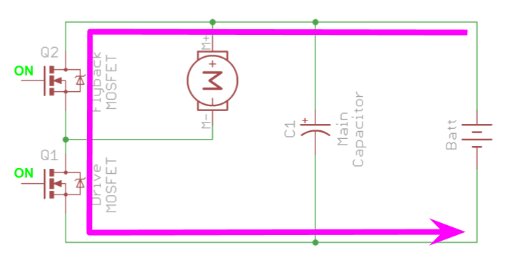
Current path when driving.
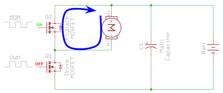
Current path during flyback.
However, there is a risk in this circuit. If both MOSFETs turn on at the same time, it will short the battery positive and negative together. This condition is called "Shoot Through".
Short circuit if both MOSFETs turn on at the same time.
Most probably you will see some flame and smoke from the MOSFET if this happens. Hence, it is very important for the MOSFET driving circuit to make sure both MOSFETs cannot turn on at the same time.
Dead-Time:
MOSFET in real world does not turn on and turn off sharply. Instead, it takes some time for the MOSFET to switch. As a result, we can't turn on the Q2 immediately right after turning off Q1 because it will take some time to fully off. Instead, we should delay a while before turning on Q2. This gap is called "Dead Time". Without dead time, shoot through will happen and although it's only for a few nanoseconds to microseconds, the current might be large enough to fry the MOSFET instantaneously.
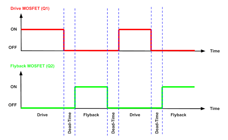
Dead time in synchronous rectification motor driver.
Do we still need the flyback diode in this case? YES! We still need the diode to conduct the flyback current for a short while during the dead time until the flyback MOSFET turns on. Fortunately, every MOSFET already has a body diode built in and extra diode is not needed.
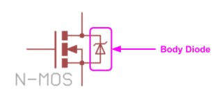
MOSFET body diode.
However, if you are using Bipolar Junction Transistor (BJT) instead of MOSFET, the flyback diode cannot be omitted.
Uni-directional motor driver with synchronous rectification using BJT.
This is applicable to bi-directional motor driver too. External flyback diode is only needed for BJT based motor driver and can be omitted for MOSFET based motor driver.
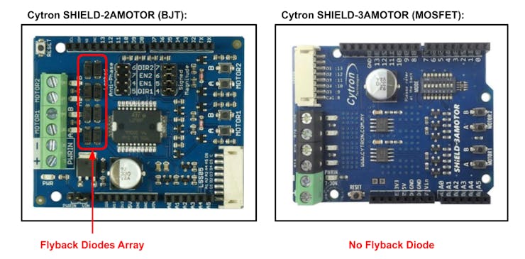
BJT vs MOSFET based motor driver.
Another advantage of synchronous rectification is the motor driver is capable of braking the motor through dynamic and regenerative braking. Read on to find out more.
Diode Rectification vs Synchronous Rectification
Here are some comparisons between diode rectification and synchronous rectification:
Diode Rectification:
- Simpler circuit and lesser components.
- Lower efficiency.
- None regenerative, no braking for motor.
- Cannot control motor speed accurately.
- Application: Fan, Water Pump, Conveyor...
SynchronousRectification:
- Much more complex circuit with more components (Need to handle switching dead-time, motor regeneration, etc).
- Higher efficiency.
- Regenerative, motor can be braked.
- Able to control motor speed accurately.
- Application: Servo Drive, Mobile Robot, Electric Bike...
Dynamic Braking and Regenerative Braking
Some of the motor drivers in the market label themselves as "Regenerative Motor Driver". When the motor speed is faster than it's commanded, it acts as a generator. These motor drivers are capable of feeding back the energy from the motor to charge the battery and effectively brake the motor. This is similar to technology used in hybrid vehicle. When the vehicle is braking, kinematic energy of the vehicle is converted into battery charge.
Anyway, this sounds more sophisticated than it really is.
Dynamic Braking:
We already knew that if we short both motor terminals together when the motor is rotating, current will flow in the opposite direction due to the Back-EMF and this will brake the motor. The current is limited by the motor internal resistance and the wiring resistance. The motor kinematic energy will be dissipated as heat through the resistance and this is dynamic braking.
We can do this easily with synchronous rectification motor driver by turning on the flyback MOSFET (MOSFET conducts current in both direction when switches on).
Current path during dynamic braking.
Regenerative Braking:
If the energy from motor can be fed back to the power source instead of dissipated as heat, that becomes regenerative braking.
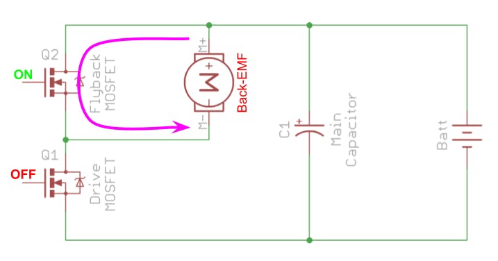
Consider the previous case for dynamic braking where the motor is running and the flyback MOSFET is on, current is flowing through the flyback MOSFET producing torque in opposite direction.
What happen if we turn off flyback MOSFET and turn on the Drive MOSFET instead? The braking current cannot be interrupted and it needs to keep flowing in the direction. As a result, the current will flow into the battery and back to the motor through drive MOSFET as opposing to drive current and this will effectively charge the battery.
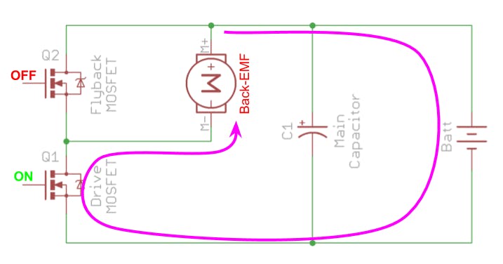
Current path during regenerative braking.
In short, when we reduce the PWM duty cycle when the motor is running, the motor will be switched between dynamic braking and regenerative braking. The ratio is depending on the PWM duty cycle. It can be from pure regenerative braking (100% duty cycle) to pure dynamic braking (0% duty cycle).
All of this happens automatically and the regenerative braking is just a by product of synchronous rectification. There is no rocket science in it, really!
Problem of Regenerative Braking
Regenerative braking increases the efficiency of a motor driver by feeding back the excessive energy to the battery and provide braking power to the motor so that its speed can be controlled more accurately. Sounds like very good huh?
However, the dark side is, regenerative braking will create problem, or dangerous when a switching power supply is used to power the motor. Unlike battery, most of the switching power supply cannot absorb current from motor regeneration. This results in the rise of voltage and the amplitude is dependent on how fast the motor decelerate and its load. Consequently, the power supply might trip or shutdown if it has over voltage protection. If the voltage spike is too high, it will kill the motor driver or power supply if the maximum voltage rating is exceeded.
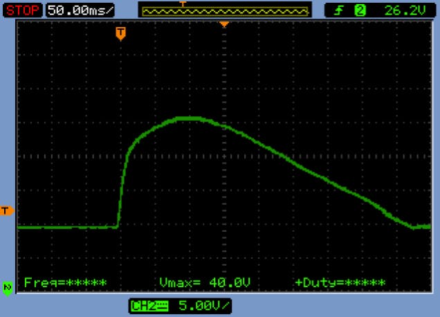
Voltage spike caused by motor regeneration.
As can be seen from the oscilloscope plot above, a 24V powered motor can cause a voltage spike up to 40V during regeneration.
We received quite a number of emails from our customers asking is it possible to just put a TVS diode to clamp the voltage spike? NO! TVS diode is only good for clamping the spike that happens in few microseconds to milliseconds such as clamping ESD. From the plot, we can see that the voltage spike will take a few hundreds milliseconds to settle down. This is also dependent on your motor deceleration and load. TVS diode definitely could not handle this and will burst into flame.
So, is there any solution? Using switching power supply is essential especially for industrial application.
Parallel Battery with Power Supply:
We can connect a rechargeable battery (preferable SLA battery) with same voltage rating in parallel with the power supply.
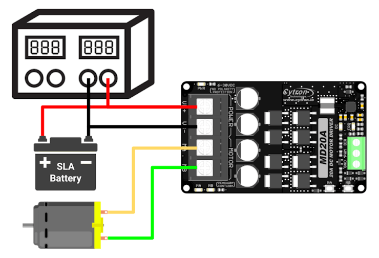
Parallel battery with power supply.
During motor deceleration, the battery serves as a reservoir to absorb the current from motor regeneration. Good thing about this setup is when the motor accelerate, battery can help to supply current to motor and reduce the load of the power supply.
However, the battery can be quite bulky and is not practical for application in consumer product. Furthermore, batteries do have lifetime and require regular maintenance.
Shunt Regulator:
Shunt regulator is a device that designed to clamp the voltage spike by dissipating the energy through some high power resistor. It works similarly with a TVS diode except that it can handle much more power for a longer duration. Besides, shunt regulator also has more accurate trigger voltage than a TVS diode.
Please note that the trigger voltage must be slightly higher than the power supply voltage.
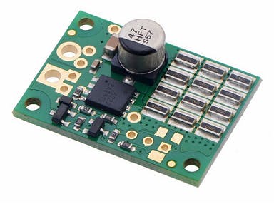
Shunt regulator designed by Pololu.
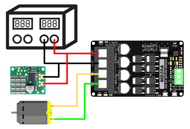
Parallel shunt regulator with power supply.
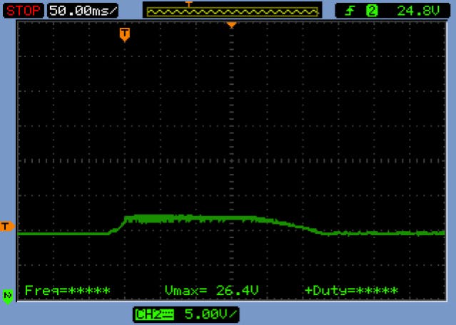
Voltage spike is clamped at 26.4V with shunt regulator.
We can see that after installing the shunt regulator in parallel to the power supply, the voltage spike is clamped at 26.4V.
Conclusion
I think that's enough for part 1. So far we have covered electrical model for a brushed DC motor, uni-directional motor driver with diode rectification and synchronous rectification, regenerative braking, its problem and solution.
In part 2, I will talked about bi-directional motor driver and H-bridge.
Stay tuned!
Questions, praise or criticism? Leave your comment below. :-)
Thanks for helping to keep our community civil!
This post is an advertisement, or vandalism. It is not useful or relevant to the current topic.
You flagged this as spam. Undo flag.Flag Post
Your post is currently under review by our moderation team. The review process usually takes up to 48 business hours.
You can track your post's status in the "My Content" section of your profile. Once approved, it will be published and visible to others.

Thank you for contributing to our community!