Woody Mk1 - A small Indoor Ground Reconnaissance Robot

Introduction

This is my first robot, well in its current state it is more a remotely controlled vehicle, as it does not have any self-contained intelligence in it. Its name is Woody, as the frame is made of balsa wood. Woody is controlled via a very rough but still powerful remote control, which comprises basically a breadboard, a battery, an XBee module, an 3.3V power converter, a cheap thumb joystick and some loose wires. I have chosen to build my own remote control, as I don't like those bulky and heavy two joystick remotes widely used for RC cars, planes, boats, etc. When trying out the remote I also noticed the fun of having a simple control with one hand. Before we go into details have a look on the video and the photo set attached.


Overview of remote control and robot

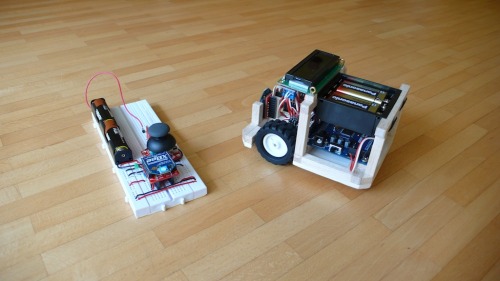
Photo 1: Overview of both devices, remote conrol (left) and robot (right)


Photo 2: Close-up of the robot with both Pololu-motors and the TB6612 double H-bridge controller


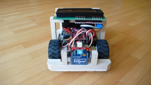
Photo 3: Front side with XBee module and motors (ball caster not visible)


Photo 4: Right-hand side with battery compartment and Propeller Plattform USB from GadgetGangster


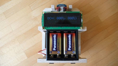
Photo 5: Top view on LCD display with duty cycle info for left and right motor


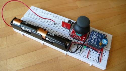
Photo 6: Breadboard-level remote control


Some more details

So far I only use three of the eight available cogs (or cores) of the Propeller: Cog 0 for the high level stuff like booting the other cogs after start and driving the serial COM with the LCD display. Cog 1 is responsible for the COM with the remote control and Cog 2 is doing the PWM for both motors.

The most interesting aspect for the remote control is this special mode of operation of the XBees, where permanently the ADC or DIO lines are read and transmitted without need for an extra microcontroller. This is the reason, why the remote can be made with so few elements. The thumb joystick deliveres two voltages, these are digitized with 10 bits and the result is transmitted every 50ms to the other XBee on the robot. As both XBees are paired with their unique serial numbers, no interference is expeced from other COM devices at 2.4 GHz.

Cog 1 then permanently reads the remote control transmissions, processes them into suitable PWM values (including indication of motor revolution direction) and puts them into a hub-memory register. Finally this register is permantly read by Cog 2 to get the latest values of the motor duty cycles. As Cog 1 and Cog 2 by definition never can access the mentioned hub-memory register at the same time, there can not be any access conflict or race condition. That's all basically.

Way ahead

Now as the motor control is done I am going to focus on video capture and processing with Woody and its Propeller based heart. For me it would be nice to have a video data link over the XBee-to-XBee communication line, say from a small CMOS camera (bw or colour) to a cheap 3" LCD video display on the remote control. I recently found one for about 20€ on Ebay. If this works well and if there is even more space or bandwidth for a second camera, then the way is open for a true stereoscopic video transmision into video glasses, capable of displaying 3D data. Right now I have the Zeiss Cinemizer Plus or the upcoming Zeiss Cinemizer OLED in mind, as most of the FPV video glasses (e.g. Fatshark RCV922) are not stereoscopic to my knowledge.

A platform for further works towards a remotly controlled ground reconnaissance vehicle

  • Actuators / output devices: 2 motors
  • Control method: RF Remote Control
  • CPU: Parallax Propeller
  • Power source: 9v battery
  • Programming language: Spin and Assembly
  • Sensors / input devices: none right now
  • Target environment: Indoor or outdoor

This is a companion discussion topic for the original entry at https://community.robotshop.com/robots/show/woody-mk1-a-small-indoor-ground-reconnaissance-robot

xBee ADC

I’m buidling the remote for this car the same way as you: noµC, only the xBee that reads ADC and sends the value over to another xBee. But can you clarify how the ADC value is submitted to the µC on the receiving end? I can’t seem to find clear documentation on that matter :confused:

XBee ADC

Hello Simon,

basically all you need is the official XBee doc: http://ftp1.digi.com/support/documentation/90000982_B.pdf There is also a small note in the official Propeller Guide (ISBN 978-0-07-166450-9) on page 232, which originally pointed me to this interesting XBee feature. But now to the facts:

As you already might know, the ADC and DIO readings are transmitted only in API mode, no further XBee programming needed. Here is an example of a reading I wrote down for my own clarification:

7E 00 12 82 00 13 A2 00 40 64 DD 66 1C 00 01 06 00 01 FC 01 F8 C8 … so we have 22 bytes in total. I get such a reading every 50ms. Now to the meaning of the bytes:

  • 7E the API start delimiter. Your UART receiver software shall wait until it reads exactly this byte sequence.
  • 00 12 length of the frame in bytes counted without checksum (the last byte: here C8) and start delimiter
  • 82 API identifier. Can be 0x82 or 0x83 depending on the XBee addressing mode (16 bis or 64 bit)
  • 00 13 A2 00 40 64 DD 66 the sender address (my XBees operate in 64 bit addressing mode)
  • 1C received signal strength in neg. dBm. Here 0x1C == -28dBm
  • 00 options byte
  • 01 06 00 01 FC 01 F8 finally the ADC data (see below)
  • C8 checksum

The final ADC data (01 06 00 01 FC 01 F8) is to be interpreted in the following way:

  • 01 means one sample per Tx frame
  • 06 00 channel indicator (bit field coded, see XBee manual p. 13) here: ADC0 and ADC1 used, no DIO pins used
  • 01 FC Finally the voltage reading at ADC0. Here 0x1FC = 508, which is about the half of 1023 (max ADC value)
  • 01 F8 Finally the voltage reading at ADC1. Here 0x1FC = 504.

Obviously the joystick was in middle position on both axis.

Take care, if you want to transmit ADC and DIO data at the same moment, the length of the frame becomes longer, as the digital data then precedes the ADC data with two more bytes. But this is best viewed with the help of the X-CTU terminal, if you lower the sample time so something like a 1 or 2 seconds. 

Well that’s the full story - hope this helps.


Best regards,

Michael

Cute car-like robot! Keep it

Cute car-like robot! Keep it up!

Thanks for this

Thanks for this clarification! But I still have a few questions: how do these bytes reach the µC ? Through serial? If so, how do you store and process them? Serial.read won’t be enough, I guess? Or am I wrong?

EDIT: just realised that you do not use arduino, never mind about the Serial.read question…

Yes, the bytes are received
Yes, the bytes are received by the Microcontroller in the given order. You need to have a means for UART serial communication. In my case with the Propeller this is easily done in software with some assembler commands. You need to be able to read each and every byte as seen above in the given order.


I like the position of the xbee ,and generally the whole robot is cute .

Thanks. I’ll do my very best.

To be honest, the position
To be honest, the position is merely a result of installation space constraints. But afterwards I noticed how cool it looks with the XB in front.

Thanks again

Thanks again for the info! I’ll have something to think about, I guess :slight_smile:

Nice first bot

Clean design- love the balsa framework.  Another thing that could be fun with your setup is to use an accelerometer breakout (Pololu, Sparkfun, etc have them) on your breadboard to control movement via tilting, but the joystick definitely rocks. 

Thanks. I think I have

Thanks. I think I have already seen on YouTube a hacked Roomba controlled via a tilted handset or even by tilting a MacBook. Looks pretty cool, but I doubt the accuracy of robot control against an ordinary RF remote or my thumb driven one-hand-remote.

The joystick has got even one more feature, that I almost forgot - it’s the select button. Using this button, I could be able to toggle through different movement operation modes of the robot. Something like an “accuracy movement” mode at half duty cycle with less sensitive reaction on joysick movement would definitely be nice to have…

Nice, maybe even toggle

Nice, maybe even toggle headlights on and off.

On second thought…

I think it would be sweet to control the main body via tilt with accelerometer and control a nerf cannon with pan/tilt servos using the joystick to move and button to launch. I love getting creative.