When I power up the SSC, and select “All = 1500” on Lynxterm, the legs positions are pretty close to Figures 6, 7, and 8 of the Tutorial. HOWEVER, in order to get the final alignments recommended in these figures, I find I need to adjust the Width parameter in addition to the Offset parameter. For example, my parameters for the Front Left Knee are offset = -40, width=1364.
So my question is: Will having initial width values different from 1500 affect the operation of the Phoenix code, or do I need to go back and physically adjust the servo horns (‘gasp’) so that I do not need to use the width adjust ments?
If I remember correctly, the SSC-32U allows for an offset of ±100 µs per channel. When using a servo with a pulse range of 500-2500 µs over a range of about 180° that would mean ~±9° of play from center position. See the SSC-32U manual page 26 for details.
If your starting position requires a different width value it means your robot is not assembled properly … so, yeah, you’ll have to remove horns and replace them (center servo shafts to 1500 before reassembling!). The point of the offset is to compensate for the shaft only having 24 teeth over 360°, leading to 15° between each “position” possible for the horn-shaft pairing. If your horn is placed more than one tooth off of where it needs to be than the offset won’t be enough to correct the position fully.
The Phoenix code uses 1500 as the center value so your motor’s should line up with that pulse width (using proper assembling and offset for “in-between teeth positions”).
I hope that info helps!
Sincerely,
As a side effect, if your robot needs different starting width than 1500 to move properly the
Mr. Scharette - a follow up clarification/question if you don’t mind:
Alignment of the horizontal hip servos (“perpendicular to chassis”) is pretty straightforward.
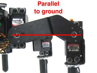
For the vertical hip servos, Figure 7 of the Tutorial shows that a line between the center of the servo horn screws should be “parallel to ground”. This alignment results in the “C bracket” attached to the vertical hip servo being angled “up” a bit (NOT parallel to the ground). So that is what I will aim for when I re-adjust the vertical hip servo.
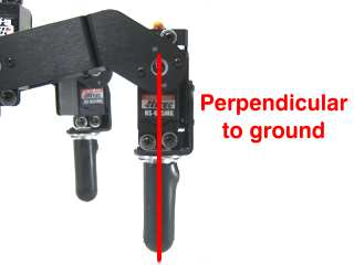
For the knee servos, I will aim for “perpendicular to the ground” as shown in Figure 8 of the tutorial.
These changes/adjustments will all be made with the servos set to 1500.


 … so, yeah, you’ll have to remove horns and replace them (center servo shafts to 1500 before reassembling!). The point of the offset is to compensate for the shaft only having 24 teeth over 360°, leading to 15° between each “position” possible for the horn-shaft pairing. If your horn is placed more than one tooth off of where it needs to be than the offset won’t be enough to correct the position fully.
 ) :
) :