

1/27/09
Hello, this is my first robot on LMR, but i previously have built 1 other robot.
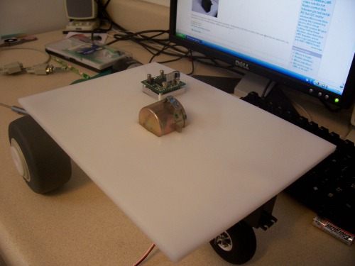
This robot is my first robot that i designed myself. It is a three wheeled robot with a base made of a 1/4 inch HDPE. The two rear wheels are the drive wheels and are on a 7/16 inch diameter axle made from the shaft of a baton (not my baton).The front wheel is not powered, but it's axle is attached to a Futaba servo from Parallax to steer the robot. To keep the wheels on the axle, they will be duct taped where the wheels will be to make it thicker and slip resistant (Update: Now using packing tape). The controller is a BS2 from Parallax on the Basic Stamp carrier board. I am using the HB Motor controller (from Parallax) to controll the drive motor.
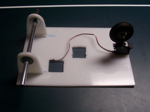
Shown in the picture above is the underbelly of the robot. The hole cut out to the left is for the motor controller which has a fan that sticks down. the hole on the right is for the drive motor. Eventually I will need to cut a slot out for the drive belt.
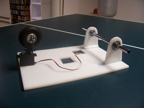
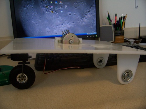
That is the same thing from a different angle. It shows the front wheel and mounting better. The servo is for now mounted with servo tape but that will soon change as the tape is too wobbly and unstable.
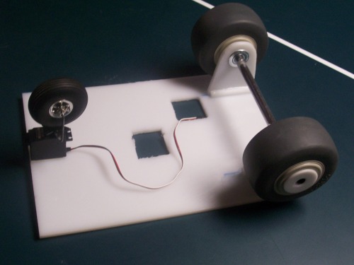
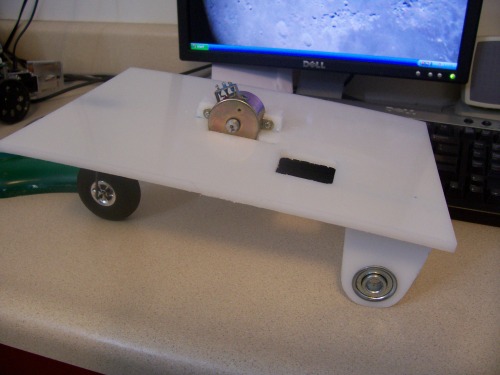
That is the same thing only the wheels are set on the axle minus the duct tape holing them on tight.
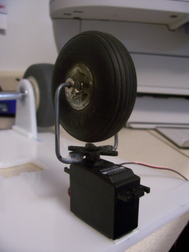
The above is an up-close view of the front wheen assembly. Nothing fancy but tricky to bend:) Not sure where the tire came from, I found it in a box of model airplane stuff.
Update 1/28/09:
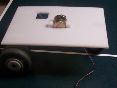
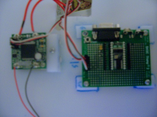
This pic shows the base with the motor and motor controller Setting in their holes that were cut out. They aren't attached yet as there is more work to be done on the mechanical part of the drive systems but i thought i'd show you how it will look.
2/4/09: Got the Servo re-mounted and the motor finally mounted on. Will have pictures soon but im at school right now so i don't have my camera. Friday i don't have school so i expect to get the rest of the drive system complete and maybe even start to get my microcontroller mounted :0 !!!!!
After that i still need to get the motor controller mounted and hook everything up before i can start doing real tests and post a video too. Still not sure what sensers to add first but im thinking of adding two bumper switches on the bottom of the robot as cliff detection and a sharp IR senser on the top of the robot for wall and object detection.
Later That Day...
Ok im home Now. Let there be pictures!!!!
The above is a side view of the new mounted motor. Note: My desk is not that badly tilted to the side, i just tilted the camera so that the base appeared to be level sive the rear wheels aren't on.
That's a better view of the motor mounts. Just a couple of blocks of hpde that i skrewed the motor into. For those who haven't used HDPE before and want to use it, HDPE is not self tapping, so you have to drill a hole slightly smaller into the plastic to drill the skrew into. Mount like that however are very solid and reliable if you need to attage a non-glueable somthing to HDPE.
30 min later...
Well, i got the rest of the drive system up and ... sorta running. The catch: that sorta was telling you that it isn't running with the back wheels on. Why? They're just too darn heavy. That unidentifiable motor is unidentifiably too weak to turn such heavy wheels, so as you can see on the first video, the robot goes nowhere by its self, and when i give it a little push, it rolls the slightest bit farther than expected and really doesn't want to go backwards. So now i need smaller, lighter wheels with the same diameter to keep the robot level. Doh!!!!!
Picture of the failure:
A top view.
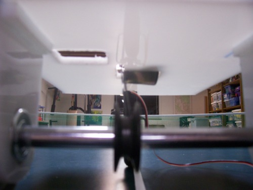
A blurry bottom view:) In it you can see the bottom of the motor, the drive belt, and the pully on the drive axle.
Update 2/21/09
I just ordered a Faulhaber 1524E006S123 motor with 15/5S141:1K832 gearhead and HES164A encoder
as seen on this page in the components section. Also, I got some gears and a timing belt and as backup, some plastic hollow wheeles that I really don't want to have to use. I'm hopeing that the motor will be powerful enough. The encoder is a plus.
I'm starting to think about what sensors I want to start out with. I know my goal is to be able to map out surroundings the use the Wavefront algorithm to do some navigation, but that is too complicated to start thinking about right now.
Update 3/22/09
Got parts a while a go but for got to post update. I ended up getting the following:
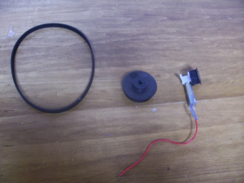
from left to right: Timing belt, large gear, and motor with small gear attached to motor head
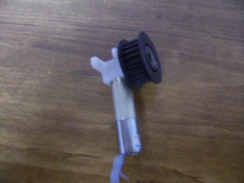
motor close up
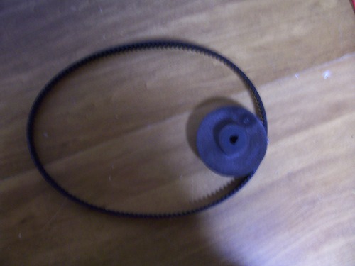
gear and timing belt close up.
All that I have left to do is find a drill bit the exact size of my drive shaft and take the large gear to the drill press so that it will fit onto my axel. Im hopeing thatthe stronger motor and the beefier belt will be able to push my robot.When I got my new belt,I discovered it was much too long to put the orot at the current hole, so instead i am mounting the motor at the very front of the base and using the previous motor's hole to put wires going from the bottom to the top of the base through.
Update 4/4/2009
Well, once I got the drill press running, I got about an milimeter into the gear and the bit was already dull, so I got a couple of hight strength bits designed for cutting metal. With those I got about 1/2 way through the gear and the metal center piece got so hot it actually started to melt the plastic, so I just popped the metal piece out. Now I need to find something to use for a center piece for the gear with a 1/2 inch bore. I thought about using a wood piece but I am not shure. Things to think on.
Update 4/5/2009
Last night after I posted the above i decided on wood. I found a plank of wood and cut out a disk with a hole saw. Then I epoxyed it into the gear, and drilled out a 7/16 inch bore for the axle and it works beautifully. Now, after switching to packing tape for friction fitting the wheels (Duct tape wasn't working), all i have left to do for the drive system is to mount the motor, and I'l be good to go. After that it's just a matter of mounting the Motor controller and the Stamp.
Pictures:
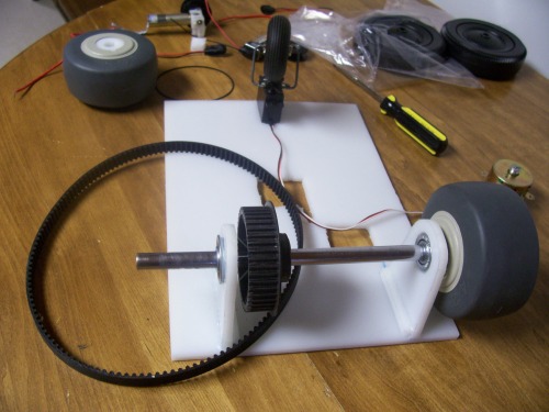
A picture of the whole axle assembly. Only thing left off is the left wheel.
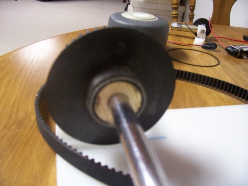
A picture of the wooden bore-thingey. Home made and fits like a charm.
Update 4/6/09
Drive system complete! Other than a few tweaks here and there, ship it. Look at top video to see all systems functioning upsidown. Cool stuf. In it i show all of the drive system working, the BS2 and HB-25 motor controller functioning, and i put a few objects on the wheel just to show it is really moving and not photo-shoped. Soon I will have a video posted of Trixie right side up running, but I don't have time right now.
Update 4/25/09
Sorry I haven't updated in a while. Been very busy with stuff. Every thing is now mounted. I also soldered two 3-pin headers on the BS2's proto area for convinient connecting.
Also I ordered $60 worth of stuff for a sharp IR sensor assembly. I ordered the Sharp IR, a servo, a proto board and some extra, A Picaxe and supporting parts, and some other parts to connect it all together. Add $40 of shipping total and I spent a whopping $100 for one sensor. It adds on fast.
Nothing Yet :)
- CPU: Basic Stamp 2
- Power source: 2 9 volt batteries (many options)
- Programming language: pbasic
- Target environment: indoors
This is a companion discussion topic for the original entry at https://community.robotshop.com/robots/show/trixie
