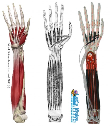
The Replicated Hand - Prototype 1 (TRH-P1)

Hello everyone, this is my first post on this great site and also my first robotics project. For my final year Mechatronics undergraduate project I decided to try and replicate the human hand and forearm in a mechanical form, taking into account all the bones, muscles and tendons. This is preferably for applications in, but not limited to, telerobotics. I have named this project The Replicated Hand, which is a tribute to The Replicated Man quest of Fallout 3, of which I'm a huge fan! :D


For my project research I looked at the functional anatomy of the human hand and forearm in detail, and identified 40 muscles and 29 bones. I also did some research on various artificial muscle actuators, as well as the history and application of telerobotics to better understand the subject area.
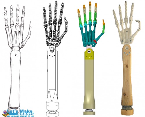
 

 Skeletal design

Skeletal design and construction


I focused on the right hand for this first prototype. With the design I started with the skeleton, first sketching and then moving on to CAD modelling in Solid Edge. I looked at each of the 29 bones, the joints they form as well as the origin and insertion points of all the muscle tendons. The final design consists of 19 skeletal components with 23 joints. The bones are colour coded for reference in the CAD model, e.g. orange for distal phalanges. The degrees of motion and limitations in movements are based on measurements from my own right hand.
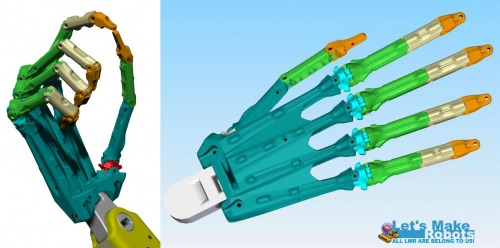
 

 Hand design

Hand design


28 muscles were designed to help achieve the basic movements of abduction, (hyper)adduction, pronation, supination, flexion and (hyper)extension in the limb. These are divided into 10 intrinsic muscles on the hand and 18 extrinsic muscles on the forearm.


Muscle research, design and implementation


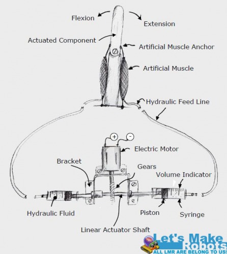
Early on in the project I decided to use fluidic muscles because of their life like function. But instead of the traditional pneumatics that need (expensive) pressure gauging and valves, I designed a hydraulic volume displacement method for controlling the flex/relax of the muscles. And as shown below, this design also aimed to reduce the number of motors to half the number of muscles. This also lets two opposing muscles act together as in biology (e.g. biceps and triceps).


Concept design for the actuator assembly and muscles


I used simple DC brush motors (cheapest) with simple limit switches to determine the extremes of the muscles’ flex/relax. Therefore, for the 28 muscles I needed 14 motorised linear actuators.


This is the type of linear actuator I ended up using in the project


For control I eventually went with the Seeeduino Mega controller board which offers about I/O 70 pins.
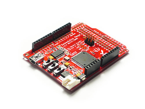


Seeeduino Mega

Seeeduino Mega


 I don’t know if a similar kind of actuator assembly already exists, I couldn’t find anything similar during my research. If there is, I would really appreciate if you could please give me a name for the thing so I can look into it instead of building the whole assembly from scratch for future prototypes. Thanks!
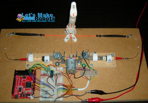
  

Actuator test 

Test rig with the first prototype of the finger to test out the joint tolerances and actuator concept


A test rig was made to test the concept and it proved to work. But with high pressures, when flexing a muscle fully, the plastic gears turned out to be the weakest point and did slip a bit. For driving the motors and changing direction I used the SN754410 H-Bridge by Texas Instruments. This is a quadruple H-bridge that can drive two motors at currents of up to 1 A at voltages from 4.5 V to 36 V. Therefore I needed 7 H-Bridge chips for the 14 motors. Oh, and the motors on the wooden boards can get quite noisy while at work.


I made the artificial muscles myself following this great tutorial I found online. The muscles consist of soft silicone tubing for the internal bladders, woven PET for the outer mesh, PVC tubing to feed the pressure and braided polyester strings for the tendons. One of the big constraints in this project was the budget of course. The hand bones and wrist was printed on the Dimensions Elite 3D printer available at my university. The forearm was made from hi-tech pine wood.
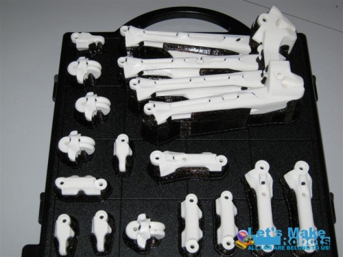
 

 Printing completed...

Some of the printed parts


I also designed custom heads that were printed, and used to securely attach the linear actuator to the syringe plungers.


 Plunger heads

The printed plunger heads attached to the linear actuator
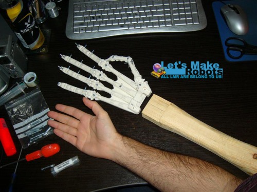
 

My.. what big hands you've got 

During the first stages of assembly for size comparison


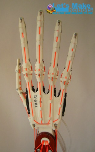
M4 machine screws and nuts were used in the wrist joints and M3 screws and nuts are used for all other joints.To hold the tendons close to the bone while channelling them to their insertion points, I incorporated tendon tubes into the design. Electrical terminator rings were used to attach the tendons to the limb.
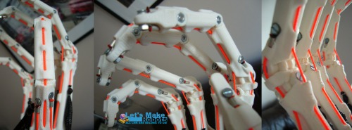
 

Fingers and tendons 

The hand assembled showing the tendons and channels


For bringing all the parts together in one structure, I assembled a ‘control cabinet’. This is a four tier structure for housing all the actuators (two bottom tiers), control circuits (third tier) and to mount the arm on (top tier). The arm is mounted by the elbow and standing upright.
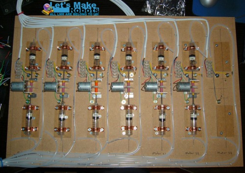
 

 Extrinsic actuators

The actuator tier for the extrinsic muscles being assembled
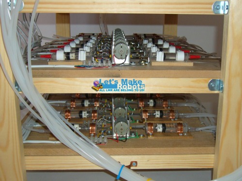
 

 Actuator tiers

The actuator tiers assembled and placed on the control cabinet


All the tubes and wires were then hooked up and the assembly was done!
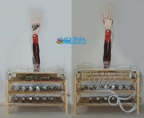
 

Prototype 1


The final assembly


The finished hand


 The project was finished on time and just about on budget. I also got a great mark for it! :D


But unfortunately a comprehensive control programme is still lacking at this point (programming is not my strong suit). Luckily I got to keep the whole thing so I want to make some modifications for improvements, and try to get some coordinated movements out of it before really setting out on the second prototype.


Room for improvements

This was just the first prototype and in many ways a proof of concept. But actually making the thing did highlight some design flaws that need improving on. For example filling the syringes, tubes and muscles with water; after a while air bubbles will start to form. And standing water promotes the growth of algae. It was also a bit difficult to thread all the tendons through the dedicated holes in the bones, especially in the wrist. The clearances for attaching the origins of the interosseous muscles are also a bit tight. The channels for the tendons in the wrist are also a too elaborate with too many corners, and as a result a few tendons struggle to move. Also with all the piping at the base of the arm there was no real room for the two muscles at the bottom for pronation and supination. Therefore those two muscles and their associated actuator were left out for now.


Ideas for improvements in the second prototype:

·         Improvements on the actuators, such as using servo motors and more durable gears

·         Other hydraulic fluid, about the same viscosity (or less if possible) as water

·         Completely redesign the wrist

·         Simplify all tendon tubes to minimise restrictions in tendon movements

·         Custom PCB to tidy up all the wires

·         Better control programme!

·         More compact actuator housing/control cabinet

·         Maybe some mobility, such as wheels


In the spirit of open source and freedom of information, I’ve decided to share my CAD files, if you want to have a go at this. All I ask is that you keep me posted on how and where you use it, and you give credit where credit is due. It would be nice to see what someone else can do with this. All files are in the .stl format, which is a bit more universal than the .par files of Solid Edge, and exported with a high level of detail.


TRH-P1 Components (Part 1)

TRH-P1 Components (Part 2)

TRH-P1 Components (Part 3)


Files are compressed in .rar files. Total size: 134 MB


UPDATE: It seems STL files are not easily read by some CAD packages. I've converted the assembly to a STEP file, which also saves a LOT on space. I've also put the zip file on Dropbox, so the link should stay a live for a lot longer:


TRH-P1 Assembly (Step Files)

TRH-P1 Assembly (STL Files)


Let me know when the link doesn't work anymore by leaving a comment.


Happy trails partner!

;)

A mechanical replica of the human hand

  • Actuators / output devices: DC brush motors, fluidic muscles
  • Control method: Seeeduino Mega controller board
  • CPU: ATmega1280 (16 MHz)
  • Operating system: N/A
  • Power source: 18V 2A bench power supply
  • Programming language: C++
  • Sensors / input devices: Limit Switches
  • Target environment: indoor, outdoor

This is a companion discussion topic for the original entry at https://community.robotshop.com/robots/show/the-replicated-hand-prototype-1-trh-p1

I love it!
I love it!

Like Oddbot said, you could

Like Oddbot said, you could use the Mega, which has many more i/o pins. But if you go that route, I HIGHLY suggest getting the clone version by Seeedstudio, it has 12 more pins, and a few extra badass capabilities.

http://www.seeedstudio.com/depot/seeeduino-mega-fully-assembled-p-438.html


You could also look into using shift registers, which has 8 pins you can use for input or output, depending on which you get, and only use 3 pins of the Arduino. But the good thing is, you can daisy chain the registers together to attach up to 16 chips with just 3 pins of the Arduino. Look at :

http://www.arduino.cc/en/Tutorial/ShiftOut

But keep in mind as well, most of the 74HC595’s can only source or sink about 20ma, unless you get the High Current, which can switch up to 150ma per channel. But you can always use Darlington Transistor Arrays, has 8 transistors in a chip, just connect the inputs of that to the outputs of the 74595’s and you’re almost halfway there! lol

While it does add some complication… it definitely opens the numbers of pins you can get using an Atmega8 or something comparable. The only bad thing about getting the Mega… is there’s no real upgrade in speed. You get a WHOLE lot of extra pins, and extra space… but I’ve only seen 1 (one) sketch that could barely fit on a Duemilanove… but there’s just no speed upgrade. You can add extra EEPROM for cheap… which can pass the amount on the board for just a few bucks.

aaahhh… The day we all get

aaahhh… The day we all get 3D printers… :smiley:

Cool project!

A few suggestions…

This is a fantastic project - beautifully done, my friend! :slight_smile:

I’m an electrical engineer from Charleston, West Virginia, USA. This project (anthropomophic hand/arm) is the very reason I became an engineer. I have designed something very similar in 3D using AutoCad 2010 - which I plan to have printed in 3D also, but I’m not yet satisfied with my design (can’t figure out how to get those nice curved contours to my fingers).

Anyway, from an electrical engineering standpoint, I have a few suggestions.

1) Regular DC motors are (probably) not going to give you the torque you need to actuate the movements. I think that your single-actuator-for-opposing-forces + hydraulic-fluid-displacement method is fantastic; however, I would suggest using servo motors for four reasons:

a) adequate torque - A servo motor is nothing more than a DC motor with gears (for adding torque) and a negative feedback circuit (for control).

b) precision control - By feeding a particular frequency (or inversely, duty cycle), you can achieve very smooth and precise control.

c) I/O pin usage - Servos only require ONE I/O line per motor!

d) feedback - Servos have an internal circuit which provides negative feedback - positioning the motor to a precise position (negating the need for optical encoders, limit switches, or other feedback mechanisms - which, in turn, reduces the number of I/O pins required to just the single line for sending the PWM signal to the servo). Why do you think all the animatronics guys use servos in the special effects business? Because it’s the best solution, that’s why!

One last thing… I know that most people here at LMR are mad about Arduinos. And don’t get me wrong; Arduinos are great for beginners - along with Basic Stamps, etc. But when you’re ready to get serious about controlling this hand; you need to bite the bullet, switch over to PIC chips (far cheaper with WAY more low-level control), learn PIC Assembly language (or C if you’re lazy), and do it the correct way from the beginning. (Yeah, I know; I’ve probably ticked a few people off. Sometimes the truth - aka my opinion - hurts.) If you want to know more, Xabel - or want to discuss this further, send me a private message.

Good job! …I need to check out EAGLE!

Aaron

A few other thoughts…

I thought of a few other things after going back and reading some of the other posts…

CaptainObvious suggested using shift registers. A similar idea would be to use a DEMUX (demultiplexer) if you’re looking to expand your I/O ports. Something like the 74138 (google it) would work nicely. By using a binary code (ex: 101 in binary = 5 in decimal), you can use relatively few I/O pins to send data to more output devices. 2^N=M, where N is the number of pins you’ll use up on your microprocessor, and M is the number of output devices you’ll be able to control. The 74138 3-to-8 DEMUX chip, for example, only requires you to use up 3 I/O pins on your MPU and get 8 lines in return - plus a fourth necessary to actually send the data (2^3 = 8). You can also get 4-to-16 chips and/or combine chips to get more. This doesn’t seem like a huge advantage with small numbers of I/O pins; but once you get into much larger numbers, it really pays off. …But again, I’ll remind you that by using servo motors, you can do away with the need for all those extra I/O pins altogether.

Also - if you do decide to go with servos, rather than trying to control them all yourself (which can get rather cumbersome for 28 PWM signals), I suggest looking into a servo controller - which can control MANY servos! You can also get a nice GUI (Graphical User Interface) program to coordinate all of your complex movements simultaneously - which is what the pro’s use. If this interests you - as it should - I suggest checking out Gary Willet’s webpage: www.willettfx.com. He does some pretty amazing animatronics work (using servos, of course) and even has an excellent 4 DVD set on the whole process. He’s extremely thorough and down-to-earth, and he includes all the manufacturers and model numbers of everything you’ll need. You can also watch his videos (the same ones as are on the DVDs) for free on YouTube by searching his name there. I’ve corresponded with him - great guy! …I think there are about 14 or so video segments on his animatronic process on YouTube. I suggest watching them all, but only the last few are specifically about servos, servo controllers, and software.

…And if/when you get to the point that you want to have a custom, professionally manufactured embedded circuit designed to control your hand/arm, let me know. I do this on the side; I’m good at it, and I’ll do it for next to nothing - for projects I deem worthy (such as this one). But first you have to decide exactly how you want to control this thing mechanically and electronically.

Aaron


pressured syringes
From playing around with syringes, I can tell you they are not designed for endured usage, or high pressure. Depending on your muscles’ demands, you might have to find a more suitable hydraulic cylinder/piston assembly.

Syringes?

Rik is right; you want real hydraulic cylinders - not plastic syringes.

Aaron

Thanks :smiley:

Thanks :smiley:

WOW!

Thanks for the great response! Sorry for my late replies, just finished my exams… hectic times…

Thanks
Thanks :slight_smile:

Looks promising!

Thanks, the Seeduino Mega looks very promising indeed. I’m thinking this with the H-bridges as suggested by OddBot.

No problem…

No problem, Xabel… I understand (about the hectic times). I have a couple big side projects which are going to tie me up for the next couple of weeks; but if you’re interested in discussing this further, let me know.

By the way… I like your motor-driven hydraulic / pneumatic air bladder muscle design (which is being used on some high-end artificial hand / arms), but I have a couple comments about that.

1) These air bladders (though a very simple concept) are prohibitively expensive for hobbyists like us. The alternative is to make your own. Maybe the homemade versions work great; I don’t know. But my suspicion is that they would be difficult to make and work well.

2) The alternative to that is to do what they do in the special effects industry and simply use the servos to move wire cables - bypassing the air bladders altogether. Yeah, I think that the air bladders are definitely cooler and closely resemble the look and function of real muscle tissue, but I wonder how difficult good results are to achieve in your basement on a hobbyist’s budget.

Just a few thoughts… Good luck either way! I can’t wait to see your finished hand / arm!

Aaron

Daar leer ek nog 'n ding!

Thanks for the info. This is more a proof of concept than anything else. The budget is tight for this project but I’ll get proper hydraulic cylinder/piston assemblies for the next prototype (along with the suggested servos). I’ve actually looked at proper cylinders, but quite more expensive, I can get a couple of syringes for about £1. :stuck_out_tongue: These won’t be for prolonged/endured use and I want to maybe include in the control that the muscles rest at minimum pressure in the cylinders when not in use, i.e. in a neutral position.

Wow, thanks for the great suggestions

This was also the reason I wanted to become an engineer: To make robotic prosthetic hands/arms. But that’s a bit outside my undergraduate project scope, so I’ve looked into telerobotics, especially like bomb disposal (Surrogates), and try and develop a dexterous hand for that, later adding telescopic vision feedback and datagloves etc. The human hand is just such a beautiful mechanism…

Since you’re into the same thing, I used an old version of Primal 3D Interactive Hand that I borrowed from my friend for the research, then there’s also OpenSim, and a couple of websites like Anybody Technology, Visible Body (used to be free), to name but a few resources. Oh, and this one. The University of Washington has also done interesting work on the movements of fingers (video 1 2 3). Then there are the ones for inspiration, like The Shadow Robot Company, Touch Bionics, NASA’s Robonaut and just to freak you out a bit, this high speed hand… where will it all end? lol

I was just about to ask if this actuation concept has been used somewhere else. I’m afraid budget constraints will force me to go with the DC brush motors for Prototype 1. I can get one of these motors, with the bracket etc. already assembled, for just under £5 (discount when you buy 10+), and that’s going to be about the whole budget! :stuck_out_tongue:

|x

They are advertised as “High torque linear actuators”, come with NO information, but I tested one and got a max linear force of about 200N at 1.5V 2A. Syringe piston diameter about 15mm, so this gives a max pressure of about 1MPa. But a quick test I did on one of the muscles needed about 80N to flex, so the pressure hopefully won’t get as bad as 1MPa. Syringes I can get about 3 for £1. I plan to build a little test rig this week. But I’ve taken all you said onboard, and will definitely try proper cylinder/piston assemblies and servos in Prototype 2 (along with many other planned improvements). I want to try and get proper skeletal CAD files (buy or draw myself) based on MRI scans and xrays to get the shape and dimensions right and then just modify that for the next one. With the fluidic bladder muscles I'm trying to recreate real muscles and their locations and actions, and the ones I've made so far seem pretty sound. But I want to look more into electroactive polymers and the like for future prototypes.

I just thought of Arduino boards because a mate of mine in class recommended it. But the Seeduino Mega board suggested by Captain Obvious seems like a good bet, and is only about £32 for 70 I/O pins. But I’ve never used a controller board before, can you run a motor from a board’s digital pins or would you need a motor board or something like that? I have a lot of reading up to do following these suggestions from you guys.

Feel free to upload a couple of your hand CAD images/renders. It would be great to see that! :D

No micro controller can drive a motor directly

That’s the no-part of your question taken care of.

Depending on your requirements, you need some driver. A circuit between controller and motor. This can be as straight forward as a single transistor, connecting one output pin on the controller to the motor. But that motor would only rotate in one direction and never turn back.

This is where (half) H-bridges come in. That is simply a clever combination of transistors (sometimes relays), connecting two or more controller pins to both leads on your motor. This will give you control over the direction. Plus speed if you include more complexity.

You sound like you need to start with a few small experiments before spending too much money.

Thanks for the info!

I’ll take your advice and start with some small experiments and circuits. I found this tutorial on H-bridges and DC motors that I’m going to try and see how it goes from there. Luckily I have an Arduino Duemilanove handy and got a SN754410 H-bridge for about £2.50. I’ll keep you guys updated on any progress.

Corrections and suggestions… :slight_smile:

Okay, Xabel (Is that your real name?)… Again, Rik is correct; you cannot drive a motor directly from a microprocessor or microcontroller (such as the Arduino). MPU’s (MicroProcessor Units) have I/O ports which are generally 8-bit registers (0 through 7). For example, if you set bit 2 on Port A, it would look like this in binary: 00000100. (The most significant bit, 7, is on the far left; and the least significant bit, 0, is on the far right - 7,6,5,4,3,2,1,0.) The ONE in 00000100 means that the bit is “set” to a HIGH logic level (usually +5 volts DC, or maybe +3.3 volts DC with the newer CMOS chips). Basically what I’m trying to say, is that you need to “set” a bit on an I/O port in order to make +5VDC appear on one of the output pins - which is how you send signals to external devices, e.g., LEDs, LCD displays, audio amplifiers, motor drivers, etc. (This might seem like Greek to you now, but it’s stuff you MUST know when you delve into controlling this thing. Or team up with your mate who knows about Arduinos.) …HOWEVER - and this is where Rik’s comment comes in, individual I/O lines are only capable sinking / sourcing about 20 mA (milliamps) per pin - or a total of 160 - 180 mA for the entire port. Generally, at +5VDC, your standard hobby DC brush motor will draw a few hundred milliamps (at least 10 times more than a single output pin is capable of supplying). A good analogy is like what I refered to before - Pinky & the Brain. The Brain is like the Arduino, very smart and does all the thinking but isn’t strong enough to exert much force (like driving a motor). Pinky is the “big, dumb ox” of the duo. He’s not smart enough to come up with the ideas, but he has the muscle to put the Brain’s plans into action (like driving a motor). In this analogy, Pinky is the H-bridge motor driver suggested by Rik. An H-bridge is nothing more than a configuration of switches (transistors) that direct a larger current - which is where the “muscle” comes in - to provide proper power to the motor. …By the way, you generally want to keep your power sources for your logic circuits (Arduino) and motor drivers (H-bridge) separate. You might even feed a +12VDC supply to the H-bridge to power your motor (as long as your motor is rated for up to +12VDC). More voltage for a fixed resistance (the motor windings) means more current, which means more TORQUE!!!

…Just so you know (as a side note), I was about where you are 7 years ago. I googled “robotics and Charleston, West Virginia, USA” in an attempt to find someone who knew about electronics / robotics and could basically mentor me. The search yielded ONE result - the webpage of a Computer Engineer. I e-mailed him, and he agreed to meet me in the food court at a local mall. (Keep in mind that at this point, I could barely light up an LED without burning it up!) This guy (Neil) brought with him a few electronics catalogs and a piece of wood with “eye”-hooks and screen door latches screwed into it, crudely wired together to a motor and battery to form a mechanical model of an H-bridge motor driver. He explained the principle of how it worked, and that was that. That was the last I heard from him …until 5 years later (in 2008) when I graduated with my degree in Electrical Engineering and moved to Charleston, WV. I looked him up again, e-mailed him, and asked if he wanted to start a robotics club with me. Together we founded the WEST VIRGINIA ROBOTICS CLUB (www.wvrc.us - webpage leaves something to be desired), and we’ve been good friends ever since. From the relationships I’ve made in WVRC, I’ve learned a LOT about all kinds of different aspects of electronics / robotics - microprocessors (PICs, Basic Stamps, Propellers, Arduinos, Z80s, etc), RF TX/RX, antennas, wireless communication, lasers, audio amplifiers, etc. Anyway, the point is that I was once a novice, and now I’m pretty much the go-to guy! I’m published in Nuts & Volts magazine (“Solar Tracker” - August 2009), I’ve worked on several design consults for the WV Dept. of Education (electronics kits for high schools and colleges), and I’m currently - right now, actually - designing an extremely complicated 6-layer printed circuit board for a BIG client in Chicago! For a LOT of money! (And this is just a hobby for me!) I’m also in negotiations with a local robotics company and the U.S. Air Force on an embedded system w/ PCB design project!!! …Okay, yeah, so I boasted a little (for which I expect to receive jeers from intellectually insecure people about flaunting my credentials and success), but that’s not the point. I’m attempting to provide you with a little inspiration in that even though you might feel like the task ahead of you is insurmountable, keep at it; never give up, and you will eventually succeed! I can’t tell you how many sleepless nights I’ve spent reading scores of mind-numbingly boring books and “midnight tinkering” - which usually ended in miserable failures! For every success I’ve enjoyed, there were hundreds of discouraging failures. And now, finally (at 32 years old), I’m becoming a decent electronics engineer. I feel like I’m in the “knee” of the exponential curve to success, and the future looks bright!!! You’ll get there too! :slight_smile:

Sorry for the exposition. Anyway… I hate to be the bearer of bad news, but there are some fundamental flaws in your design which need to be fixed before you proceed - one of which I didn’t notice until I saw the picture of your DC motor assembly. Take a look at the worm gear / spur gear set-up closely. As the worm gear rotates with the motor’s shaft, this causes the spur gear to rotate on an axis perpendicular to the motor’s shaft. And if the spur gear’s shaft is connected to the plungers of two syringes on opposite ends of the shaft, this is simply going to cause the plungers to rotate on an axis parallel to the axis of the syringes. Do you see what I mean? It is NOT going to drive the plungers back and forth within the syringes, creating hydraulic displacement!!! They’re simply going to spin around inside the syringes - that is, of course, if the DC motor and gears can provide enough torque to overcome the coefficient of static friction between the rubber on the plungers and the plastic cylinder of the syringes (which I seriously doubt). I went back and checked out your hand-drawn sketch to make sure it was the same set-up, and it was. My friend, this is NOT going to work as is. I’m sorry, but you’ll have to redesign. What you’ll need is a mechanism similar to the way the sway bar works in an automobile’s steering apparatus. …But before you proceed with the DC motor, let me again advise against it. Even with the gearing, I still do not believe you will aquire the necessary torque. And even if you do, you’re still missing any feedback mechanisms. Yeah, I know you could use limit switches; but why waste the I/O lines? Cough up $10 - $15 USD (£6.2 - £9.3) per SERVO - which will provide both enough torque and feedback for precise positioning. Heck, you can even get miniature servos for $3 USD (under £2) per servo, in lots of up to 20, on eBay - which INCLUDES shipping! :slight_smile: Servos are definitely the way to go here - unless you go with electric / pneumatic / hydraulic linear actuators (which are much more expensive).

About the EOD (Explosive Ordinance Disposal) robot application… Although an anthropomophic hand / arm would be fantastic for such delicate work, good luck getting the military (government) to buy ‘em!!! Military contracts go to the lowest bidder, and robots like what you’re talking about would be far more expensive than the competing bidders’ bots. Believe me; I know. I was a 19-D Cavalry Scout in the U.S. Army, and I fought in the war in Iraq in 2004. My primary mission was route clearance. We went out (in Hum-Vee’s) every day at dawn and at dusk clearing the convoy routes of IEDs (Improvised Explosive Devices). When we came across one (which we were lucky enough to spot by eye rather than being blown to bits), we usually just stood off a few hundred meters and fired it up with our .50 Cals and MK-19’s in order to blow them in place. No fancy robots - just bullets! Very rarely did EOD come out to difuse the IED. And when they did, it was just another soldier in some kind of HAZ-MAT (hazardous materials)-looking suit. Yeah, I’ve seen those expensive robots on TV, but I never saw one the whole year I was in Iraq - and it was my job to get rid of IEDs! …Anyway, good luck with that one!

About the Arduino… Seeing as you are a Mechanical Engineering student - not Electrical - and because this is a one-off project, I say go ahead and use an Arduino. It is probably the best thing for you given your level of proficiency with electronics and time constraints (or a Basic Stamp - which would probably be a lot easier for a beginner to program). By the way, I hope that didn’t come off as condescending; it absolutely was not meant that way.

About my hand / arm CAD drawings… This is an area in which you are far more proficient than I. My version is extremely well designed, mechanically (lots of well thought out design considerations); but yours is far more asthetically appealing. I have a couple screen captured images of 3-D renderings, but they’re on my work computer. I’ll try to upload them here sometime. …When I can find the time, I will definitely have to check out your design software. You want to start a robotics company? Find us some capital investors, and I’ll go in with ya! :wink:

Sorry to be Debbie-Downer about some of your design concepts; I’m only trying to help - sincerely. I don’t want you going down any blind allies and wasting time when you probably have a deadline with this design project; however, that’s usually where you learn the most!

By the way, that high-speed robot video is un-freakin’-real!!! I didn’t know that motor / sensory integration was that far along yet! …But I’m gonna have to call the bll sht flag on that cell phone flipping / catching shot. At first I thought they had the robot toss the phone and then played the shot in reverse; but you can tell (I think) that isn’t the case because upon catching the phone, the fingers (waiting at the precise catching location) only move to catch the phone - and would not supply any upward force if played in reverse. I think that they programmed that routine (as opposed to dynamic camera / motor tracking), and shot it a few dozen times 'til it finally caught it. I’m not convinced on that one.

Okay, I just blew about an hour and a half. I have to get back to my PCB design. …Is anyone still reading this sh*t?

By the way, if anyone wants to contact me directly, just send me a note. My address is my first, middle, and last names (all lower case with no spaces or underscores) at G mail. I was intentionally ambiguous about that because I know some of these sites discourage private messages because everyone should benefit from the shared knowledge - and therefore trash posts with addresses. …I think it’s obvious that I’m a sharer; so, moderators, please don’t trash my post. I’ve put a lot of useful information in here that will help Xabel and others.

Samuel Aaron Ward

The Replicated Hand - Prototype 1 (TRH-P1)
Good day

I am interested on your 3D model of hand

Would it be possible to send e-mail 3D model

[email protected]

Hello. I’m sorry but I’m not

Hello. I’m sorry but I’m not just going to give you the files, besides they are too big for an email attachment. But that said, I might consider a TRADE. If you can bring something considerable to the table we can maybe work something out.