


The Replicated Hand - Prototype 1 (TRH-P1)
Hello everyone, this is my first post on this great site and also my first robotics project. For my final year Mechatronics undergraduate project I decided to try and replicate the human hand and forearm in a mechanical form, taking into account all the bones, muscles and tendons. This is preferably for applications in, but not limited to, telerobotics. I have named this project The Replicated Hand, which is a tribute to The Replicated Man quest of Fallout 3, of which I'm a huge fan! :D
For my project research I looked at the functional anatomy of the human hand and forearm in detail, and identified 40 muscles and 29 bones. I also did some research on various artificial muscle actuators, as well as the history and application of telerobotics to better understand the subject area.
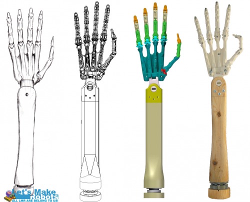
Skeletal design and construction
I focused on the right hand for this first prototype. With the design I started with the skeleton, first sketching and then moving on to CAD modelling in Solid Edge. I looked at each of the 29 bones, the joints they form as well as the origin and insertion points of all the muscle tendons. The final design consists of 19 skeletal components with 23 joints. The bones are colour coded for reference in the CAD model, e.g. orange for distal phalanges. The degrees of motion and limitations in movements are based on measurements from my own right hand.
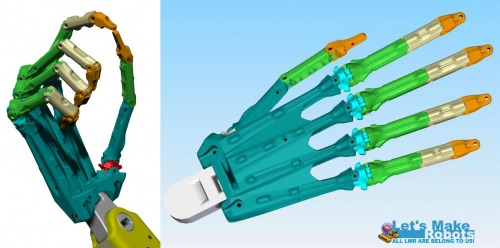
Hand design
28 muscles were designed to help achieve the basic movements of abduction, (hyper)adduction, pronation, supination, flexion and (hyper)extension in the limb. These are divided into 10 intrinsic muscles on the hand and 18 extrinsic muscles on the forearm.
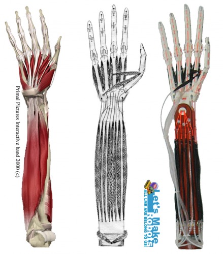
Muscle research, design and implementation
Early on in the project I decided to use fluidic muscles because of their life like function. But instead of the traditional pneumatics that need (expensive) pressure gauging and valves, I designed a hydraulic volume displacement method for controlling the flex/relax of the muscles. And as shown below, this design also aimed to reduce the number of motors to half the number of muscles. This also lets two opposing muscles act together as in biology (e.g. biceps and triceps).
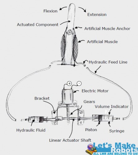
Concept design for the actuator assembly and muscles
I used simple DC brush motors (cheapest) with simple limit switches to determine the extremes of the muscles’ flex/relax. Therefore, for the 28 muscles I needed 14 motorised linear actuators.
This is the type of linear actuator I ended up using in the project
For control I eventually went with the Seeeduino Mega controller board which offers about I/O 70 pins.
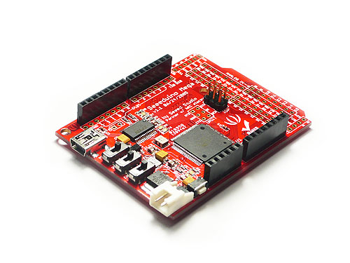
Seeeduino Mega
I don’t know if a similar kind of actuator assembly already exists, I couldn’t find anything similar during my research. If there is, I would really appreciate if you could please give me a name for the thing so I can look into it instead of building the whole assembly from scratch for future prototypes. Thanks!
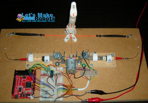
Test rig with the first prototype of the finger to test out the joint tolerances and actuator concept
A test rig was made to test the concept and it proved to work. But with high pressures, when flexing a muscle fully, the plastic gears turned out to be the weakest point and did slip a bit. For driving the motors and changing direction I used the SN754410 H-Bridge by Texas Instruments. This is a quadruple H-bridge that can drive two motors at currents of up to 1 A at voltages from 4.5 V to 36 V. Therefore I needed 7 H-Bridge chips for the 14 motors. Oh, and the motors on the wooden boards can get quite noisy while at work.
I made the artificial muscles myself following this great tutorial I found online. The muscles consist of soft silicone tubing for the internal bladders, woven PET for the outer mesh, PVC tubing to feed the pressure and braided polyester strings for the tendons. One of the big constraints in this project was the budget of course. The hand bones and wrist was printed on the Dimensions Elite 3D printer available at my university. The forearm was made from hi-tech pine wood.
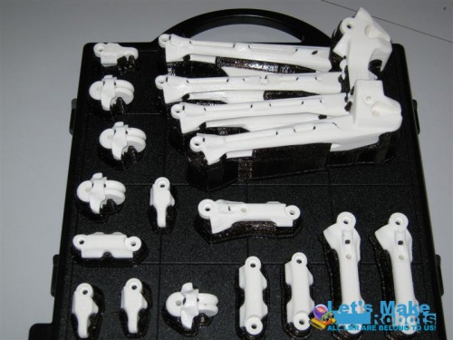
Some of the printed parts
I also designed custom heads that were printed, and used to securely attach the linear actuator to the syringe plungers.

The printed plunger heads attached to the linear actuator
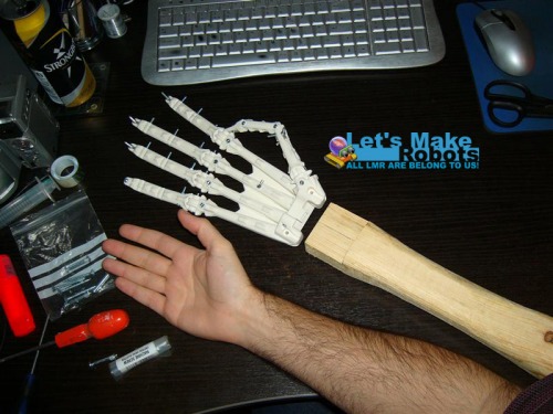
During the first stages of assembly for size comparison
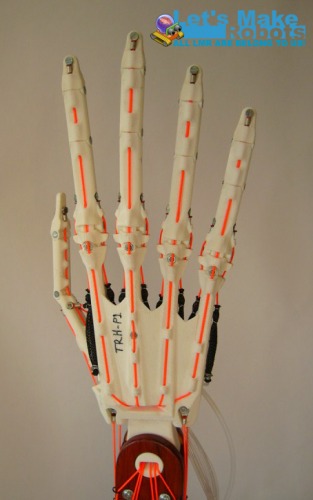
M4 machine screws and nuts were used in the wrist joints and M3 screws and nuts are used for all other joints.To hold the tendons close to the bone while channelling them to their insertion points, I incorporated tendon tubes into the design. Electrical terminator rings were used to attach the tendons to the limb.
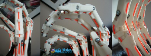
The hand assembled showing the tendons and channels
For bringing all the parts together in one structure, I assembled a ‘control cabinet’. This is a four tier structure for housing all the actuators (two bottom tiers), control circuits (third tier) and to mount the arm on (top tier). The arm is mounted by the elbow and standing upright.
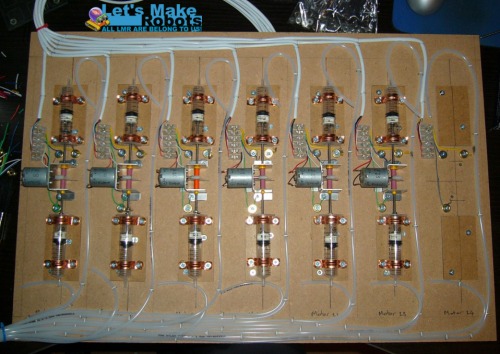
The actuator tier for the extrinsic muscles being assembled
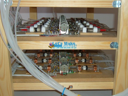
The actuator tiers assembled and placed on the control cabinet
All the tubes and wires were then hooked up and the assembly was done!
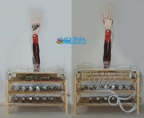
The final assembly
The finished hand
The project was finished on time and just about on budget. I also got a great mark for it! :D
But unfortunately a comprehensive control programme is still lacking at this point (programming is not my strong suit). Luckily I got to keep the whole thing so I want to make some modifications for improvements, and try to get some coordinated movements out of it before really setting out on the second prototype.
Room for improvements
This was just the first prototype and in many ways a proof of concept. But actually making the thing did highlight some design flaws that need improving on. For example filling the syringes, tubes and muscles with water; after a while air bubbles will start to form. And standing water promotes the growth of algae. It was also a bit difficult to thread all the tendons through the dedicated holes in the bones, especially in the wrist. The clearances for attaching the origins of the interosseous muscles are also a bit tight. The channels for the tendons in the wrist are also a too elaborate with too many corners, and as a result a few tendons struggle to move. Also with all the piping at the base of the arm there was no real room for the two muscles at the bottom for pronation and supination. Therefore those two muscles and their associated actuator were left out for now.
Ideas for improvements in the second prototype:
· Improvements on the actuators, such as using servo motors and more durable gears
· Other hydraulic fluid, about the same viscosity (or less if possible) as water
· Completely redesign the wrist
· Simplify all tendon tubes to minimise restrictions in tendon movements
· Custom PCB to tidy up all the wires
· Better control programme!
· More compact actuator housing/control cabinet
· Maybe some mobility, such as wheels
In the spirit of open source and freedom of information, I’ve decided to share my CAD files, if you want to have a go at this. All I ask is that you keep me posted on how and where you use it, and you give credit where credit is due. It would be nice to see what someone else can do with this. All files are in the .stl format, which is a bit more universal than the .par files of Solid Edge, and exported with a high level of detail.
TRH-P1 Components (Part 1)
TRH-P1 Components (Part 2)
TRH-P1 Components (Part 3)
Files are compressed in .rar files. Total size: 134 MB
UPDATE: It seems STL files are not easily read by some CAD packages. I've converted the assembly to a STEP file, which also saves a LOT on space. I've also put the zip file on Dropbox, so the link should stay a live for a lot longer:
Let me know when the link doesn't work anymore by leaving a comment.
Happy trails partner!
;)
A mechanical replica of the human hand
- Actuators / output devices: DC brush motors, fluidic muscles
- Control method: Seeeduino Mega controller board
- CPU: ATmega1280 (16 MHz)
- Operating system: N/A
- Power source: 18V 2A bench power supply
- Programming language: C++
- Sensors / input devices: Limit Switches
- Target environment: indoor, outdoor