SERVO-BOT-1

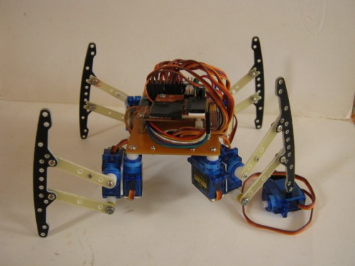
my 1st "servo" walker, my other walkers where BEAM based :) Basically just a hardware upgrade, did not like my 1st build, some hardware issues etc etc..

some parts used from my left-over tamiya parts :)


will update SOON!

more on leg mechanics:


walker

  • Actuators / output devices: 8 9g. servos
  • Control method: RF Remote Control
  • CPU: PIC16F676
  • Power source: 8.4V Li-Ion
  • Programming language: Hitech C
  • Sensors / input devices: none atm
  • Target environment: indoor flat surfaces

This is a companion discussion topic for the original entry at https://community.robotshop.com/robots/show/servo-bot-1

Nice walker.Are those legs

Nice walker.

Are those legs old bumpers? Always nice with another PIC user :slight_smile:

thanks

 yup they where ‘bumpers’. just lying in the corner of my parts bin, useless haha so I had to use them… regarding PIC code, not entirely mine, had a friend of mine help me code it. Im still a noobie with Hitech C.

Hey, I like it! Please do

Hey, I like it! Please do update the page with more info soon.

I’m very interested in seeting the detail of the linkages for the legs. How did you support the lower parallel strut on the servos? 

Also, just a small tip. There’s a lot of noise in the background of the video. Like a huge fan running or something. Try to avoid that next time. ; j

If you look careful, you’ll

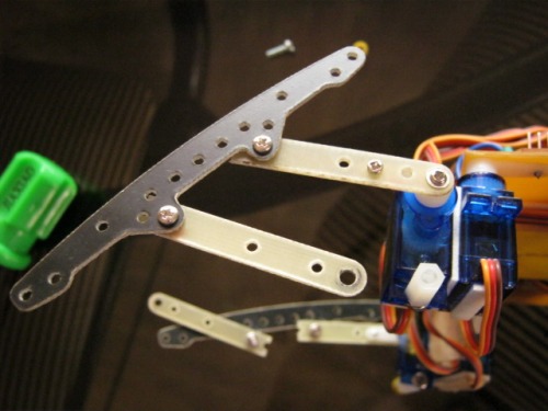
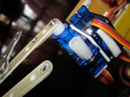
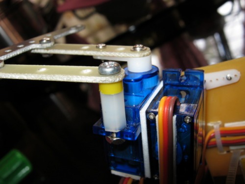
If you look careful, you’ll see that the lower strut is mounted on a bolt and a thick plastic washer or extender in the mounting hole of the up/down servo. Easy and effective. Well done! I can do the same thing with a uServotino board I guess… if I use the mounting holes to mount the pivot servos and I don’t allow the servos to go under the board. Kind of what I wanted to do with the coffee can robot. My problem was that I had the struts too shortand when the legs were up 2 pivot points would align and the leg would be able to rotate freely.

yeah, thats exactly how I

yeah, thats exactly how I did it… im using a nylon spacer/bushing… same height with the servos output shaft/horn… close up pics coming up SOON… kinda busy at the moment.

Thanks for the updated

Thanks for the updated pictures; that makes it clear.

I can see the struts are not perfectly parallel, but I guess it works fine despite that. What a simple and excellent idea!

yeah.not parallel.reason?

yeah.not parallel.reason? the tamiya bumper/s already had holes in them. really quick fix. plus I was not in the mood to drill holes. If I Did,maybe i’d offset them a bit because my bits here are a bit dull. besides, the hole in those fiber boards are equaly spaced relative to each other. :wink: