SEA RENDERING

This is Mark II of the Whirligig project https://www.robotshop.com/letsmakerobots/node/16995 code name SEA RENDERING (it’s not actually a code name, just an anagram for my name :-) )

The purpose of this robot is to have it log water depths along a predefined set of waypoints. It stores its data on memory sticks or on SD cards. The estimated runtime is about 24 hours and with a top speed of 3km/h it will travel roughly 72km. With a log entry for every 10m this would give us over 700 depth measurements   with full GPS reference.

Most of the control system has been moved from the original Whirligig to save cost and time.

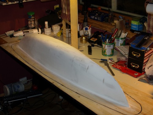
The hull was designed in the free version of DELFTship http://www.delftship.net/ and built this winter. With the split mould I can produce a second hull in matter of days.

The original plan was two hulls working in pairs as a catamaran with a solar panel on top. This can still be done but two robots working independently we can cover a larger lake on shorter time.

Some images from the hull build
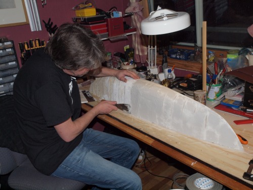
Adding fiberglass to one half of the mould
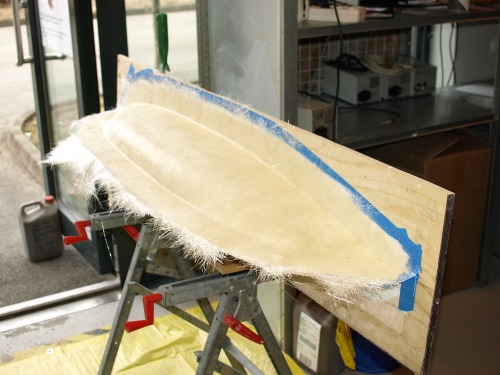
Mould completed
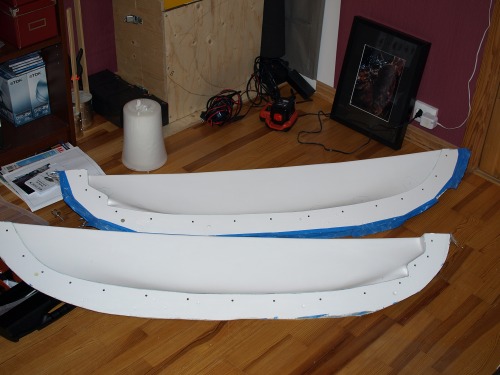
The first casting
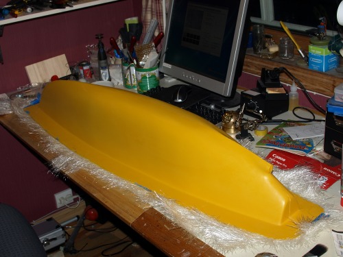
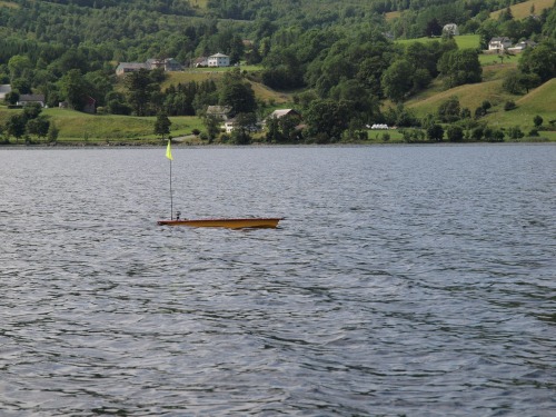
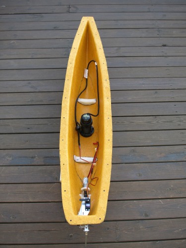
Here are some pictures from the complete robot

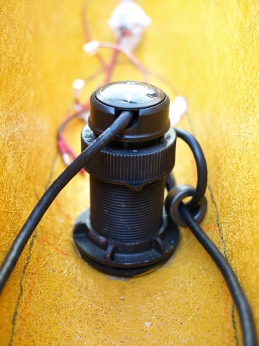
Transducer

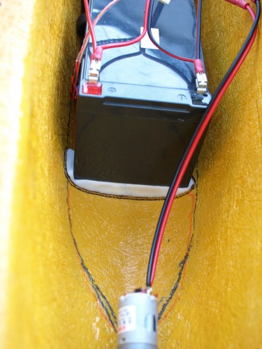
Polymorph beddings for the batteries
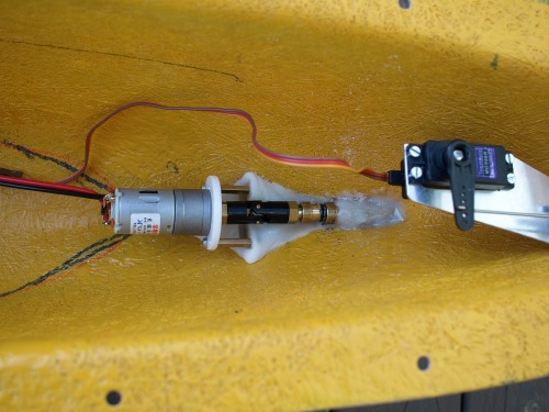
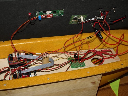
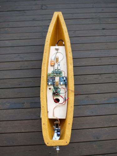
Control system

Some electronics in the lid
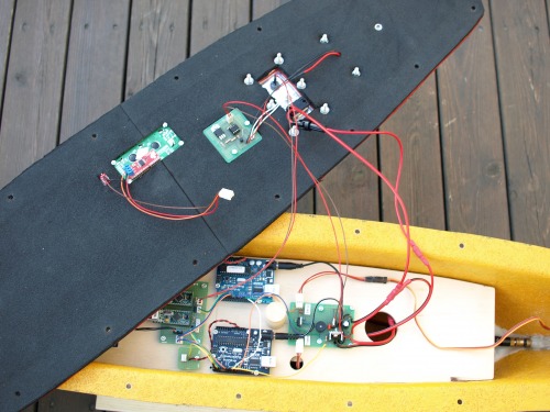
The waypoints are entered using my adaptation of the Ardupilot tool. A great application that lets you interactively add waypoints to your list. This list is then copied onto the SD card and the robot is ready to run.
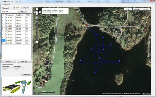
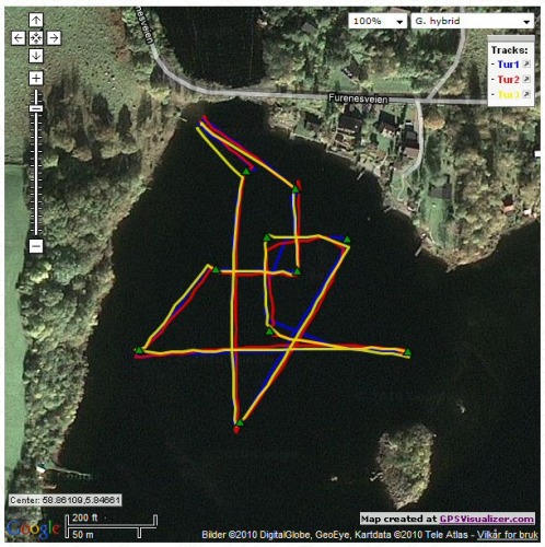
I run this routing 3 times and this is a GPS visualization of the log. The green markers are the waypoints.
(one of the log files are attached)

My brother (a professor at the University of Oslo) that will be using this robot, then run these 3 logs in something called  "Thin plate spline" http://en.wikipedia.org/wiki/Thin_plate_spline to see if the depths we logged made sense. And this is what he came up with.
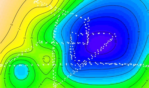
All in all this project seems very promising.

Update 28/6-2010

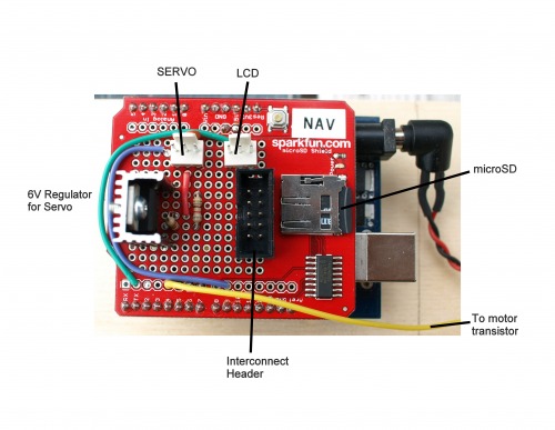
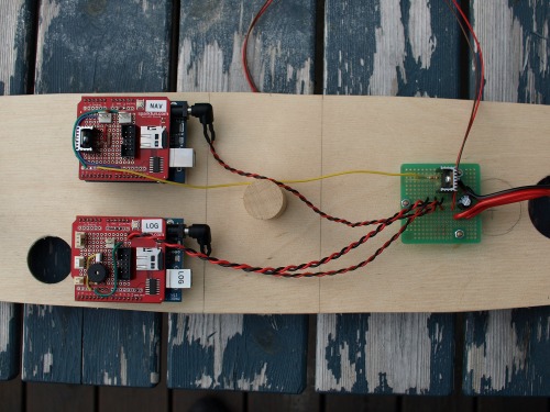
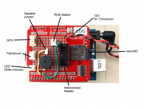
After having had some problems with the VDIP1 USB interface I decided to go for the microSD shield from Sprakfun http://www.sparkfun.com/commerce/product_info.php?products_id=9802 .
Now the whole thing looks much cleaner and is probably more robust.


Update 11/7-2010

This weekend my brother and I went to the lake ‘Riskedalsvatnet’ to do a full scale test. The full waypoint routing had 337 waypoints and a total length of 18,1km.
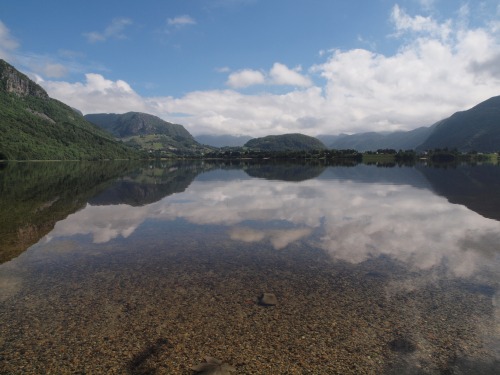

The traveling speed of the boat is about 3km/h so the mission should have been completed in about 6 hours. As this was the first full scale test and we had some uncertainties on where the shore line actually where, we decided to split the trip into 3.
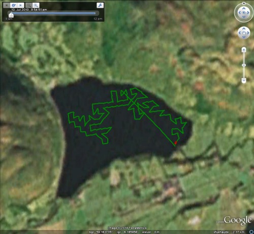
This is the first segment of the mission.
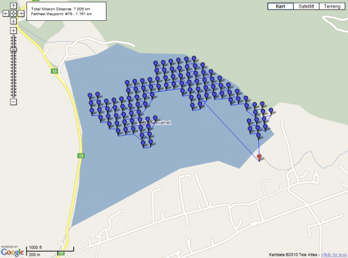
This is how the boat run

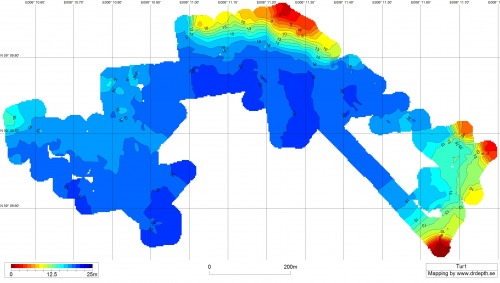
And this is an Dr.Depth rendering of the depths we got.
After all segments where completed this map was generated in Dr.Depth
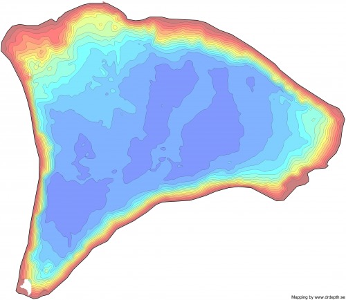
A full size map in b/w is attached


UPDATE 14/7-2010

Added the Arduino sketch if anyone want to have a look.

Measure water depths in lakes

  • Actuators / output devices: 12V 1000 RPM motor, servo based rudder
  • Control method: autonomous
  • CPU: Aruino Duomilanove 328 x 2 and PICAXE
  • Operating system: Arduino C++
  • Power source: 2 each 12V 12Ah lead batteries
  • Programming language: C++
  • Sensors / input devices: GPS, digital trancduser
  • Target environment: Lakes

This is a companion discussion topic for the original entry at https://community.robotshop.com/robots/show/sea-rendering

Very cool. I love anything

Very cool. I love anything with a GPS on it. You have probably seen this man’s blog? http://diydrones.ning.com/profiles/blog/list?user=3um9qjnkq5rxo if not, it is of the same topic.

That’s a new blog for me,


That’s a new blog for me, thanks.

Im working on a similar to

Im working on a similar to this one project but the chassis its quite different .

Some drastic redesign of the

Some drastic redesign of the hull. Looks a lot more energy “friendly” Was that the reason to redesign it or did the other hull cause more undesired effects?

Awsome

very nicely designed and built.

i love UAV’s and ROV’s, currently working on a UAV at school so anything of this kind has my immediate interest.

love your work

Joker94

chassis material

What did yo use to make the chassis (the yellow thing)?

The yellow thing is Gelcoat

The yellow thing is Gelcoat and on that there are 3 layers of fiberglass and epxoy.
The hull is made in the split mould I made first.

The main reason for

The main reason for redesigning it was the share weight of Whirligig, fully loaded it weight 50kg. The second reason was to have a system that could run from solar cells on a later phase. That was not so easy to do with Whirligigs current design.

Love to see it. Hope you

Love to see it. Hope you post some information about it here on LMR when you are ready. so easy to do with Whirligigs current design.

Interesting project, Geir. I

Interesting project, Geir. I am planing to making something similar to measure the water quality

nice work

Very interesting project! Can you tell something more about the sensor to measure the water depth?

Martin

Line following mode?

A simple addition to its program could turn it into a line follower. Following an isobath while recording lat/long coordinates.

Airmar DST800

Hi

The sensor is an Airmar DST800 http://www.gpsmart.ca/item7002.htm 
That gives you standard NMEA 0183 sentences over a serial line.

I’m not sure I follow you

I’m not sure I follow you on this one.
The reason for mapping the lake is to build the map as none exists….

Building a map

I mean, only partly in jest, that the Sea Rendering could be programmed to search for a specific depth, say 50 m. And then stay with that depth-line (isobath). As it follows the isobath, a contour line would be produced. To be added to the map.

My guess is that such a strategy might be more efficient (for some mapping expeditions) than the scanning a grid strategy.

Can you explain what each

Can you explain what each microcontroller’s specific job is? I am guessing one is a master and 2 are slaves but what does each one do?

I must admit it is not as fancy as that

One Arduino is programmed to reformat and log information from the transducer and GPS. The only connection to the second Arduino is a line pulled high when logging is confirmed and we are ready to run the routing. The second Arduino handles navigation and logs each waypoint as we pass them. On calm water the accuracy is very good; most of the waypoints are passed in a distance of 1m or less.

This might seem as a waist of Arduino’s but it makes the programming and debugging much simpler. The plan is also to use the boat on other tasks, then it is easy to leave the navigation system in and change the logging Arduino to do something else or have a completely different system installed.

The PICAXE (poor thing) sits in the lid. Its only task is to measure ambient light an flash the lantern at intervals when it gets dark.  

Ok so they are just about

Ok so they are just about completely independent of each other. (I thought that was a lantern light on top) I have one other question. I see what appears to be the EM406-a GPS but do you have a compass module? I would think the GPS would get bad heading data when turning to the next waypoint. 

the programm you wrote

The programme you wrote is open-source or not?

And if its open-source from where can we download it?