Ronnie - Arduino robot project

Hey folks! This is my first robot of this kind. Orginally I wanted to use a different controllerboard with everything built onto it already, but programming it so it works just the way I wanted without timers conflicting, wrong distance readings from the SRF05 and so on, I finally settled on the Arduino Uno.


First video:

Ronnie will drive around as long as nothing is in it's way. If he comes close to an Object, he looks around to find another way. Then he turns left or right depending on how much space he has got.


The second video shows Ronnie driving around with updated code. Now he scans the area in front of him while he is driving instead of first stopping and then deciding which way to go.


This is an ongoing project and I'm going to update the post once in a while. 


To do:

  1. Let it scan the area in front of it and avoiding obstacles.
  2. Add a compass module for course correction
  3. Add wireless communication


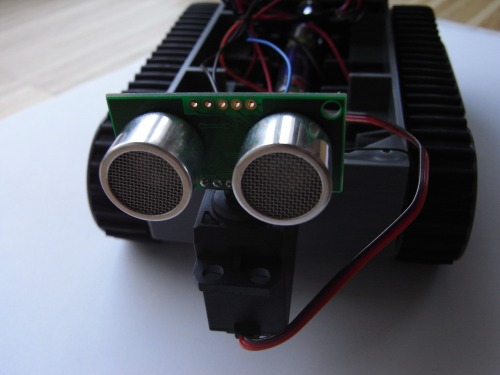
The SRF05 mounted on a servo:


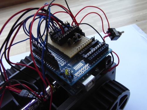
Motor controller L293B and Arduino Uno:

Comments and feedback appreciated!

So long


Torrentula

EDIT 2011/09/08:

I added a RGB status LED and a battery charge display.
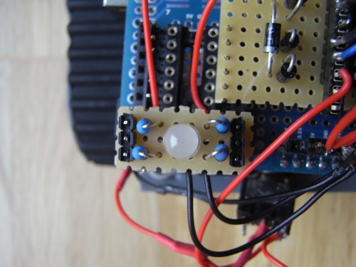
 

The status LED:


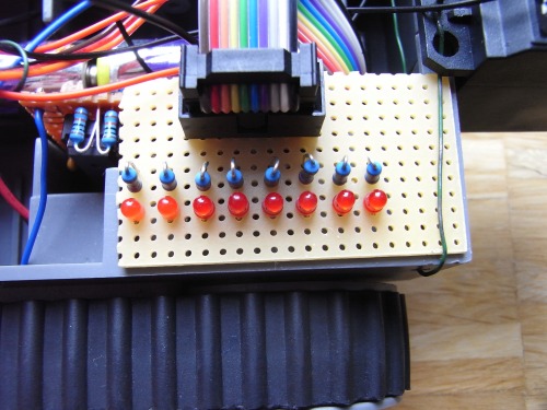
The battery charge display:


And the circuit board:

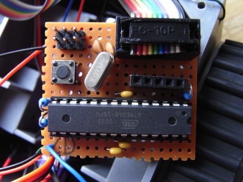
It is an ATmega8 running at 16MHz. 2 10kOhm resistors form a voltage divider which halves the battery voltage. The output of the voltage divider is read by the ATmega8 and then computed. The LEDs are lit corresponding to the voltage levels between 4.5V and 3.6V.

Thanks to majikstone and his robot modullo.


EDIT 2011/09/11:

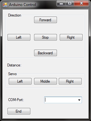
I have written a little Visual Basic program that allows me to control the bot via the serial connection. The file attachment called "control.pde" is the software for the arduino.

A screenshot of the software used to control the Arduino:


EDIT 2011/09/011: Upon request I'll post my code:

botscan.pde = The software used for autonomous roaming

control.pde = The software used to control the bot via serial connection 


Navigate around via ultrasound

  • Actuators / output devices: 2 geared motors
  • CPU: Arduino Uno (atmega328)
  • Power source: 6 AA-Batteries
  • Programming language: C
  • Sensors / input devices: SRF05 Ultra Sound Module
  • Target environment: indoors

This is a companion discussion topic for the original entry at https://community.robotshop.com/robots/show/ronnie-arduino-robot-project

Motor speed measurement

Can anybody tell me, how I could measure the speed of the motors? One of the motors runs faster than the other one, thats why I have to measure the speeds of both motors so I can let them run at the same speed.

Torrentula

Some thoughts on measuring motor speeds…

It is not uncommon for two DC gear motors to run at different speeds. You can try opening up the slower motors and filing down any burrs on the gear, re-greasing the gears and reassembling (all a pain, and may not help that much).

You can estimate about how much faster own motor is than the other, and with some experimentation and use of PWM set the relative speeds of the motors so that the are close to matching. This won’t be perfect, but it will help.

You can add an encoder of some sort. Some motors have add-on encoders, or you can buy/make one.

However, I’ve been told that with tracked vehicles, measuring the speed of the motors with encoders may not be very effective. There is a considerable amount of slip with tracked vehicles, which won’t be accounted for.

You can get an inertial measurement unit (IMU), compass, or GPS module and use the feedback from that to provide your course corrections.

Thanks for the infomation!

Thanks for the infomation!

Your robot looks good, but I

Your robot looks good, but I would like to suggest some changes in the code.

You have three more or less identical functions. getDistanceR(), getDistance() and getDistanceL() The only thing that changes is the servo position and it would be better to have this a one function. Maybe like this (not tested)

int ReadDistance(int Angle)
{
  servo.write(Angle);
  delay(servopause);
  pinMode(sensorpin, OUTPUT);
  digitalWrite(sensorpin, LOW);                        
  delayMicroseconds(2);
  digitalWrite(sensorpin, HIGH);                        
  delayMicroseconds(10);
  digitalWrite(sensorpin, LOW);                                 
  pinMode(sensorpin, INPUT);
  duration = pulseIn(sensorpin, HIGH);                       
  return duration/58;                                     
}

And then in your main loop;

Distance = ReadDistance(80);
distR = ReadDistance(35);
distL = ReadDistance(115);

This use of a common function will reduce the code size and be easier to debug and expand.

Also I’m wondering about this servo.attach and servo.detach in your function. Is that really necessary ?

Thanks for the advice! I

Thanks for the advice! I will try your code tomorrow.

I thought of just having one function but because of debugging etc. I just copied & pasted the existing function and modified each of them. The servo.attach and servo.detach were used to give PWM-functionality back to pins 9 and 10 but that didn’t work at all so they are actually just useless snippets of code.

Tomorrow besides testing your code I will clean up the code, remove unnecessary parts and the most important thing: add some comments so it is easier to understand.


Torrentula


I can’t tell you why your

I can’t tell you why your motors are running at different speeds as that can be any number of reasons. But one workaround might be to have different maxspeed settings for each motor.
Or you might try a hardware fix of adding a voltage divider on the fastest motor. Maybe by breadboarding  just the motors and having a trimpot to figure out the correct ratio.


Another thing you might consider when coding is giving your pins static names like this;

#define MotorR 5
#define MororL 3

Then you can use

analogWrite(MotorR, maxspeed);
analogWrite(MotorL, maxspeed);


and that’s easier to read then having the comments all over the place
analogWrite(5, maxspeed); // R
analogWrite(3, maxspeed); // L


But as I said, try adding different maxspeed for your motors;

#define MaxLeft 100
#define MaxRight 98

And use it

analogWrite(MotorR, MaxRight);
analogWrite(MotorL, MaxLeft);

Nice little tank bot. I like

Nice little tank bot. I like the second video when he not stop to decide where to go. I did this with my Steven X in a more advanced state too. Seems you are doing some of your electronics by yourself…

Thanks lumi^^ Yep it looks

Thanks lumi^^


Yep it looks a little messy because actually everything is connected with “flying wires” and I built the L293B breakout myself because it’s much cheaper than buying some sort of prefabricated solution :smiley:


yeah, sometimes it’s better

yeah, sometimes it’s better to build your own boards. I am going to build my own boards too soon.

can you post the vb code…im

can you post the vb code…

im new to visual basic languages…

tnx…