Ronnie - Arduino robot project
Hey folks! This is my first robot of this kind. Orginally I wanted to use a different controllerboard with everything built onto it already, but programming it so it works just the way I wanted without timers conflicting, wrong distance readings from the SRF05 and so on, I finally settled on the Arduino Uno.
First video:
Ronnie will drive around as long as nothing is in it's way. If he comes close to an Object, he looks around to find another way. Then he turns left or right depending on how much space he has got.
The second video shows Ronnie driving around with updated code. Now he scans the area in front of him while he is driving instead of first stopping and then deciding which way to go.
This is an ongoing project and I'm going to update the post once in a while.
To do:
- Let it scan the area in front of it and avoiding obstacles.
- Add a compass module for course correction
- Add wireless communication
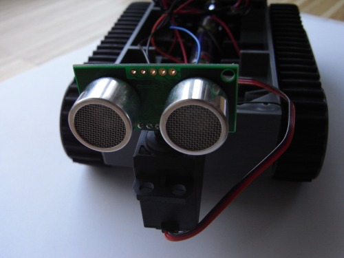
The SRF05 mounted on a servo:
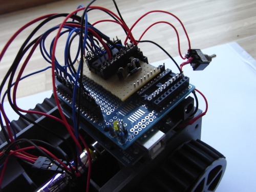
Motor controller L293B and Arduino Uno:
Comments and feedback appreciated!
So long
Torrentula
EDIT 2011/09/08:
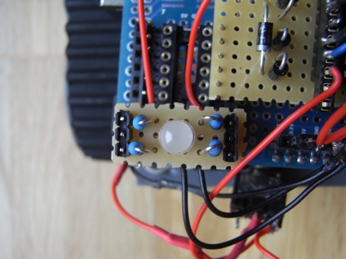
I added a RGB status LED and a battery charge display.
The status LED:
The battery charge display:
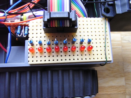
And the circuit board:
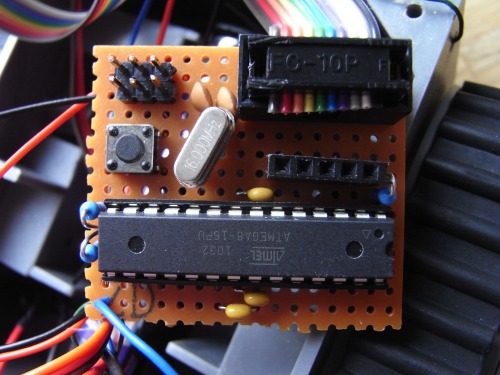
It is an ATmega8 running at 16MHz. 2 10kOhm resistors form a voltage divider which halves the battery voltage. The output of the voltage divider is read by the ATmega8 and then computed. The LEDs are lit corresponding to the voltage levels between 4.5V and 3.6V.
Thanks to majikstone and his robot modullo.
EDIT 2011/09/11:
I have written a little Visual Basic program that allows me to control the bot via the serial connection. The file attachment called "control.pde" is the software for the arduino.
A screenshot of the software used to control the Arduino:

EDIT 2011/09/011: Upon request I'll post my code:
botscan.pde = The software used for autonomous roaming
control.pde = The software used to control the bot via serial connection
Navigate around via ultrasound
- Actuators / output devices: 2 geared motors
- CPU: Arduino Uno (atmega328)
- Power source: 6 AA-Batteries
- Programming language: C
- Sensors / input devices: SRF05 Ultra Sound Module
- Target environment: indoors


