I have a rover 5 chassis (4 motors, 4 encoders). My goal to use this chasis to create a robot that drives around and is controlled by a remote.
I am new to robotics and I am unsure about how to assemble my robot chassis / what to do next. After discussion I have decided to use an Arduino Uno with this remote.
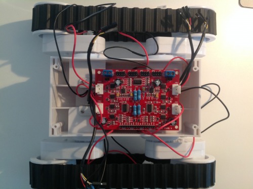
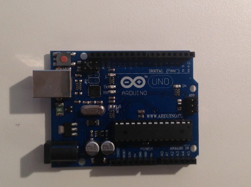
I already have the board pictured here as well as the Arduino Uno.
My Arduino Uno is the one pictured below:
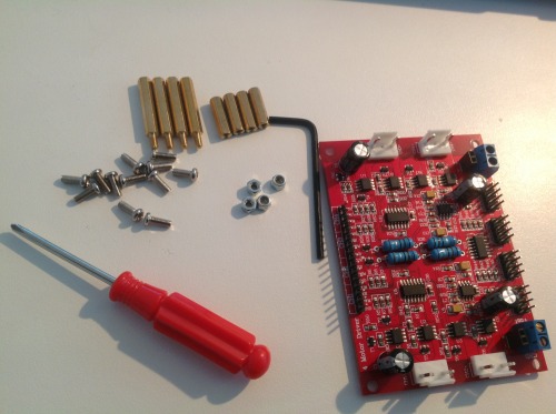
I recieved the following parts, along with the chassis itself and a battery holder capable of holding 6 batteries (total 9V)
I am now in the process of connecting up the motors with the motor driver and the Arduino Uno as mentioned on this comment, and as below:
Connect a PWN pin on your Arduino to each pin on the board that says PWM.
Take A regular digital output on the arduino to each pin marked DIR.
(Optional) Take Analogu inputs on the Arduino to each pin marked CUR.
Tie the ground and 5V of the arduino to the board. (top right by the Motor 4 output)
On the Arduino forum page, I have recieved the following advice on how to assemble my Rover 5 with an Arduino Uno
I have also been given an example code to get me started, that does not use the CUR pins or encoders, that 'should drive the robot around and give you [me] a place to start."
Click here to see the original comment with the code.
I have begun on this path, and I have already connected the PWM and the DIR pins to their locations as mentioned above.
I already have an Ardumoto motor driver shield (from Tinyos)
and an Arduino uno.
Is there a way that these two units could be used, with an arduino sketch to recieve signals from the remote and control the robot?
As I already have these products I would prefer to use them - however if another option suits my project best, I will use that product.
I am also considering using the Dagu mini Driver (as mentioned).
If I was to use the Propeller microcontroller, exactly which product (possibly from this page) would work and what could be done to make that happen.
Which of these options will have the best result on the finished product?
Also, what options are there for remotes - I have had a look but have not seen one that would suit my project. However this remote (the Phidget Mini Joy Stick Sensor) seems like a possible solution.
Hello Joccer! I mounted my rover “Acerola01”, do not know if you saw but has details, software, bill of materials and some tips mounting. Hope that helps and that you enjoy: https://www.robotshop.com/letsmakerobots/node/39969
Wiring and new materials I am very new to this and I am not sure what oddbot meant about the wiring connections. Please could you clarify exactly what I need to do to wire up the robot - please use what is written on the board so that I know which one it is. I was wondering whether the uno and the motor driver are the only boards that I need. If I need to purchase another one, please clarify. Also, apart from what came in the rover 5 box and the arduino uno, what other materials do I need to purchase (e.g wires, motor shield)
Looks like you have a healthy learning curve ahead of you. That’s an exciting part of this hobby so take your time with it. I have a lot still to learn myself. Everytime I get into a new robot project I start by searching LMR, and the internet in general, for similar projects that others have done. You may not find one exactly like what you are doing, but you may get close. For example, a few weeks ago I posted a schematic of wiring up the Rover 5 and the 4 Channel Controller but I was using the Spider as the brains. You can find it here: https://www.robotshop.com/letsmakerobots/node/40103 From that Schematic you extract what may help you but of course the Uno is different than the Spider. I can tell you that you’ll need a lot of jumper wires too. By looking at the Rover 5, 4 channel controller and UNO you be able to determine the kind (Male-Male, Male-Female or Female-Female) and about how many you need. I would also recommend taking the time to draw some sort of schematic based on what you find in the searches before wiring anything up. It will help you in the near term with lowering the potential for frying anything and help you in the long run with troubleshooting. Maybe I missed it in this post, but what is the goal of your robot? Object Ovoidance? Remote Control? Writing down what you want the robot to do will help in selecting controllers and sensors.
**My goal ** Hello OrionBot,
My goal is to control the robot with a remote control to drive around.
Eventually I will add more features, but this is my goal for now.
Thankyou for your helpful comments,
Joccer
Power In OddBot’s previous posts on my project page, he said to make sure the
5V output is connected to the 4ch motor drivers 5V logic input.
What does this mean, and where are the necessary connections situated on the two boards I am using?
Also does this mean that direct power from the batteries should go to the
Arduino’s power input or the motor driver, and if so, where?
Power Ok… But do I run the wires from the battery to the arduino or from the battery to the motor driver? The manual you gave me the link to said ‘motor suppy’ - meaning??
Its still unclear … I Think that you mean I put the power into the arduino (next to or near the USB connection) and then connect the 5V. Could you please confirm this.
I am beginning to plan the Remote control of my Rover 5 at the moment.
For my power switch I am considering getting this.
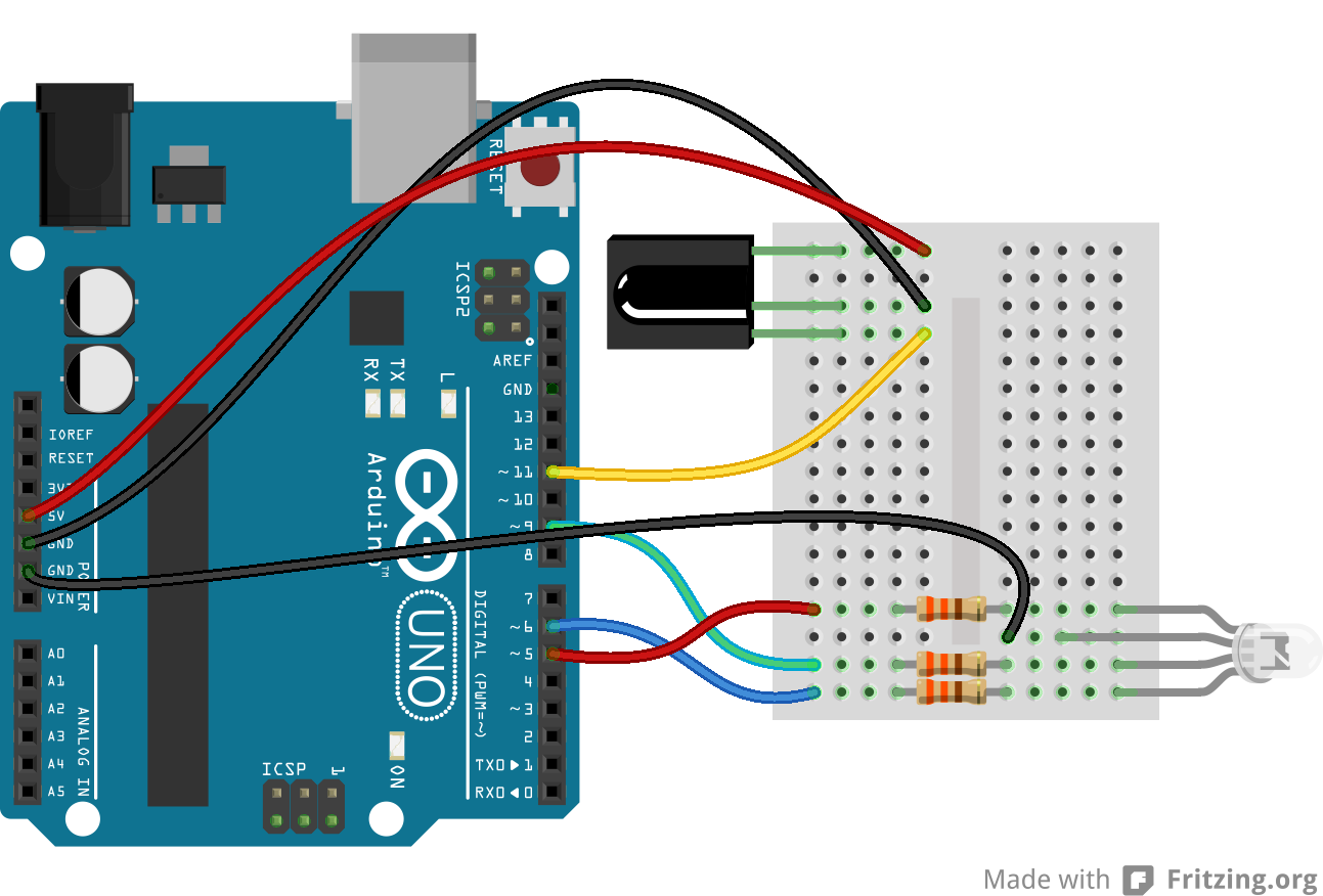
I am thinking of getting this and this to wire the remote control recieving end up like this. (the breadboard is the same dimensions as seen on the image)
As described in the lower part of my project description, I described how the wiring istructions I have been given already use 4 of the 6 PWM pins on the arduino. As this remote control reciever connection requires another 4, what is the best way to be able to connect the reciever breadboard and the other connections at the same time / is there a way to get around this?
Are these parts okay? If anyone has any suggestions/ideas please let me know.
I am assuming that the +5 as labelled on the diagram is power that has gone into the Arduino from the Vin on the left, and then out through the 5V of the arduino to both the motor driver board and the IR reciever. Is this correct?
Also, does this method of power input to the Arduino board mean that the normal place where it recievers power (via the plug near the USB connection port on the arduino) is not needed?
I strongly suggest that you get a few LEDs and switches and find some basic Arduino tutorials. They are all over the web, a quick google search for “Arduino Tutorial” should find you many.
It may not seem as exciting as a robot, but it is the beginning. Using PWM to control the brightness of an LED is similar to how the speed of a motor is controlled. Getting input from a switch is very similar to how sensors are read.
I make it a point to try out every sensor with a simple microcontroller (Arduino or a Teensy 3.1 for now) and breadboard before it touches a robot. This makes it easy to experiment with the sensor so that I know how it works and I have fewer surprises when I do put it on a robot.
Note: fewer does not mean none. In any sort of code, no matter how well written, adding new things can cause problems. However, the better written the code, the fewer problems.


