RC car

As some of you may already know, I'm building an RC car which will ignore user input and prevent a crash when necessary. It'll run on an arduino platform. I'm waiting for my parts ATM and doing whatever I can on the chassis I already had (making a motor mount, making a deck to put the electronics on, fitting in a battery...).

All pics can be found here.


UPDATE May 5th, 2011

I just finished a 5V regulator to power my Arduino UNO board. Of course I kinda forgot Arduino accepts a voltage of 6-12 V. Stupid me. Going to mount the motor the the chassis and maybe cut out the deck.


UPDATE May 7th, 2011

Got the motor mounted, and tested it... Boy this thing is LOUD and powerful!

My mailorder arrived, trying some things out with the arduino. Love that thing already :D I'm still waiting for my other mailorder with 20 transistors and 2mm pin sockets for my H-bridge and my 2nd xBee. Will keep you guys up to date!

PS: I know the servo doesn't work with PWM, made a mistake.


UPDATE May 12th, 2011

Cut out the new deck and it rocks! There's just enought space between the base and the deck to fit the battery between them. Also, I've mounted the servo and tested the steering. I'm still waiting for those transistors :( 

Update 2: mounted the Sharp IR sensors, pictures are still here.


UPDATE May 22nd, 2011

Got my transistors and soldered toghetter my H-bridge... Now I only need to solder a 5V regulator and som pin headers to make all the connections to my µC. I'll keep you guys updated.


UPDATE May 26th, 2011

I completed the PCB which holds the H-bridge and a 5V-regulator. There is a problem with the H-bridge though... I use the BD911 and BD912 transistors in my H-bridge and they are not repsonding as I expected them too. More info in the fourth vid.

Datasheets on the transistors can be found here. Can anyone confirm that I should feed 5V to the base to make these things switch on/off?

-

UPDATE July 19th, 2011

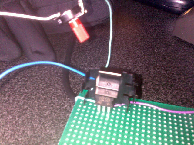
Since I couldn't get the H-bridge to work, I just tested the system with one transistor and a potentiometer (see pic). I found out that I will need a transistor to drive every transistor in the H-bridge. Too bad all radioshack-like shops in the neighbourhood are closed for vacation at the moment. Seems this project will take a lot longer than expected. I was happy to see the wheels finally spinning though :)


UPDATE March 20th, 2012

Alright, this has been some time! I kind of lost my eye on this project for a few months, but now I'm back on it! I've just finished soldering up the motorcontroller (pic below) and am now going to start figuring out how xBees work and communicate, so that will take a while to complete. At the moment, I'm kind of doing two projects at the same time, so it can be another while before I update this.


This is a companion discussion topic for the original entry at https://community.robotshop.com/robots/show/rc-car

I did the same a while back…

Check here

https://www.robotshop.com/letsmakerobots/node/16865

I did the same thing long time ago without using any microcontroller :slight_smile:

It was a fun and simple project. Looking forward to what you are going to do !

Cool!

That car of yours look very nice! But this project is more a way into arduino for me so I wont go brainless on this one :wink:

Materials?

What is the deck made out of?  I spent some time looking into materials last night, and I came to the conclusion that there are a lot of options.

honestly, I don’t know
my preferred material was triplex because of its high stifness at low thickness. But I didn’t have that so I used some scrap wood… I think it was the back side of an ikea closet one time

i,m doing the same project!

how did you calculate the torque for the propultion motor?

I never did

I see no use in calculating the torque. But if you want, I think it would be something like this: power=voltagecurrent. ‘angular velocity’=2pi*rpm. Torque=power/(angular velocity)

That should be about right :slight_smile: if you can measure your voltage, current and rotations per minute, you can calculate the torque produced using the three formulas above. I cant measure my rpm’s so I have no Idea about the torque.

mine weighs 2 kg (r/c car)

it’s so heavy that it does not move forward very fast and check this site out it shows how to build a r/c circuit for cars http://www.botskool.com/tutorials/electronics/general-electronics/building-rf-remote-control

2kg is not that much

Do you have the car posted here on LMR or do you have a picture of the motor? It really seems not that much…

no

my comps bust

It sounds like you

It sounds like you are sending your PNP transistors the wrong voltage to turn them on. Or you are not “fully saturating” them to turn them on fully. Can you post a schematic of your h-bridge?

Your BD911 transistors are NPN, and the BD912 are the complementary PNP. The difference is that an NPN needs a positive voltage bias at the base to turn on, and the PNP needs a negative voltage bias at the base to turn on.

So you will typically see your NPN transistors at the “top” of the h-bridge with their collectors connected to the battery and their emitters connected to the motor leads. The PNP transistors will be at the “bottom” of the h-bridge with their emitters connected to the motor leads and their collectors connected to ground.

To turn on the motor in one direction, you need to send a positive voltage to the base of one NPN, and a low voltage (logic low) to the base of the PNP that is diagonally across from the NPN you are turning on.

If you are already doing this, then the issue is that you are partially turning on the PNPs, instead of fully turning them on. What value resistors do you have at the base of the transistors? You may need to adjust them to get the PNP fully turned on.

Oh, one more thing. There is a voltage drop from the collector to the emitter (Vce) of each transistor. So you feed 7.2V in at the top of the NPNs, but it is going to drop 1V to 3V (depending on how much current you are running through it). The PNP transistor diagonally across from the NPN provides the current a path to ground through the motor. When the PNP transistor is fully turned on (saturated), the voltage at its emitter will not be 0V, it will be between 1V and 3V (again depending on the amount of current). So the voltage difference supplied to the motor is going to be significantly less than 7.2V.

Try turning on your h-bridge as I described above (logic high to the NPN base, logic low to the PNP base) and measure the voltage you get across the motor. If your motor is pulling less than 5A, you should get a decent amount of voltage. If you are closer to 10A, you may have to use a higher voltage battery to supply your h-bridge. 

Did it exactly like that.

First of, thanks a lot for the info!

My H-bridge is built up exactly as you described it (schematic). The problem is indeed the not being fully saturated part (as I said in the video, switch half on, bad with my words…). I originally used 5kOhm resistors for R1 and R2 but, when that didnt work, I went to 2.5 kOHm for both. Still nothing.

Do you know what value the resistors should have? is it even less? Or am I going completely the  wrong way with this and do I need a higher resistance value?

Again, thanks!

If your NPN transistors are

If your NPN transistors are turning on fully (saturated), and your PNPs are not, try a lower value for R1 and R2. I think you are safe with 1k, but I would really need to know how much current your motors are pulling.

Can you measure a few things for me?

  • What is the voltage drop from the collector to the emitter of your active NPN when the motor is supposed to be on?
  • What is the voltage drop from the emitter to the collector of your active PNP when the motor is supposed to be on?
  • What is the current going through your motor or into the collector of the active NPN when your motor is on?
  • What is the current going into the base of each transistor?

If the 1k value doesn’t work for R1 and R2, and since you are already saturating the NPNs, I think you will need to use separate base resistors for each of the transistors. I have usually seen it done with each transistor having its own base resistor. This will let you play with different values for the resistors at the bases of the PNPs to try to drive them to saturate.

When I find the time

I’ll do some measurements when I have the time (exams start in a few days). About the motor I can say the following:

  • Voltage: 6-8V
  • Unloaded current: 1.5A
  • Stall Current: 15-20 A (don’t know for sure, don’t want to fry my multimeter)

I’ll try with even lower resistor values when I get the chance…

Thanks!

If your motor needs 6V to

If your motor needs 6V to work well, you may need a higher voltage (~12V) instead of the 7.2V racing pack. You’ll see when you take your measurements and determine how much voltage you lose across the transistors.

Good luck!

The following measurements

The following measurements were done without motor attached, with 2.5kOhm resistors and with a battery voltage of 7.61V

  • NPN which gets 5V: 0V
  • PNP which gets 5V: 4.67V
  • NPN which gets 0V (GND): 7.23V
  • PNP which gets 0V (GND): 0V
  • Voltage across motor connectors: 4.32V (positive side = 5V side)

I’m guessing the problem is in the PNP which gets 5V? :slight_smile:

When I switch the 2 control pins I get the following:

  • NPN which gets 5V: 2.41V
  • PNP which gets 5V: 4.67V
  • NPN which gets 0V (GND): 7.21V
  • PNP which gets 0V (GND): 0.06V
  • Voltage across motor connectors: 4.36V (positive side = 5V side)


I think that the problem is indeed in the saturation part… When I find the time, I’ll buy 4 potentiometers, so I can easily set the right resistor value for each transistor…

Does this sound about right? Thanks!

I skimmed the datasheet for the transistors you are using and

remembered reading something about hFE. I did a search and found a page that mentioned that using the current draw through the transistor along with voltage and hFE you can calculate the value of the base resistor. The page is http://www.rason.org/Projects/transwit/transwit.htm


I hope those values are NOT

I hope those values are NOT correct, otherwise I can not use my arduino to power these transistors: I can only supply 40 mA and according to that web page I would neet 60-400 mA… Seems quite a lot if you ask me.

Searched on about the topic

Searched on about the topic and it seems to be right… Damn, now I’ll have to rebuilde the whole thing to make room for a darlington pair :frowning:

The inconsistency between

The inconsistency between the two control pin settings is weird. I’m talking about how you have essentially no voltage drop across one NPN when you turn it on, but the other NPN gets 2.41V across it when you turn it on.

Also, without the motor or some resistive load in place, I’m not sure you can really test the circuit, because the normal path of current is through the motor, and now that is open.

The link Birdmum posted was dead for me. Here’s another site with useful info on this topic:

http://www.kpsec.freeuk.com/trancirc.htm

Scroll down to ‘Choosing a suitable NPN transistor’ and it will explain how to calculate the approximate value of the base resistor.