RC car
As some of you may already know, I'm building an RC car which will ignore user input and prevent a crash when necessary. It'll run on an arduino platform. I'm waiting for my parts ATM and doing whatever I can on the chassis I already had (making a motor mount, making a deck to put the electronics on, fitting in a battery...).
All pics can be found here.
UPDATE May 5th, 2011
I just finished a 5V regulator to power my Arduino UNO board. Of course I kinda forgot Arduino accepts a voltage of 6-12 V. Stupid me. Going to mount the motor the the chassis and maybe cut out the deck.
UPDATE May 7th, 2011
Got the motor mounted, and tested it... Boy this thing is LOUD and powerful!
My mailorder arrived, trying some things out with the arduino. Love that thing already :D I'm still waiting for my other mailorder with 20 transistors and 2mm pin sockets for my H-bridge and my 2nd xBee. Will keep you guys up to date!
PS: I know the servo doesn't work with PWM, made a mistake.
UPDATE May 12th, 2011
Cut out the new deck and it rocks! There's just enought space between the base and the deck to fit the battery between them. Also, I've mounted the servo and tested the steering. I'm still waiting for those transistors :(
Update 2: mounted the Sharp IR sensors, pictures are still here.
UPDATE May 22nd, 2011
Got my transistors and soldered toghetter my H-bridge... Now I only need to solder a 5V regulator and som pin headers to make all the connections to my µC. I'll keep you guys updated.
UPDATE May 26th, 2011
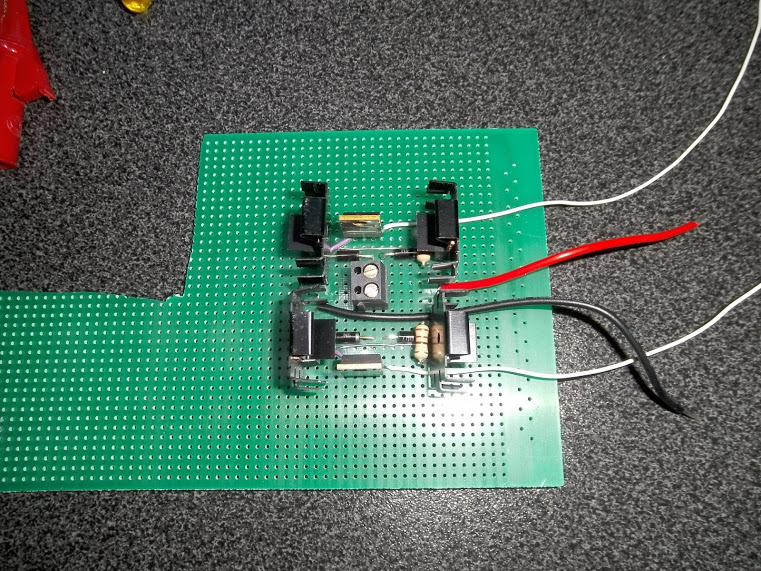
I completed the PCB which holds the H-bridge and a 5V-regulator. There is a problem with the H-bridge though... I use the BD911 and BD912 transistors in my H-bridge and they are not repsonding as I expected them too. More info in the fourth vid.
Datasheets on the transistors can be found here. Can anyone confirm that I should feed 5V to the base to make these things switch on/off?
-
UPDATE July 19th, 2011
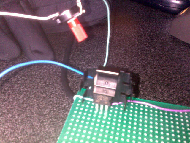
Since I couldn't get the H-bridge to work, I just tested the system with one transistor and a potentiometer (see pic). I found out that I will need a transistor to drive every transistor in the H-bridge. Too bad all radioshack-like shops in the neighbourhood are closed for vacation at the moment. Seems this project will take a lot longer than expected. I was happy to see the wheels finally spinning though :)
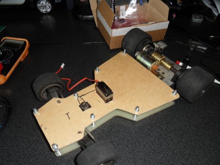
UPDATE March 20th, 2012
Alright, this has been some time! I kind of lost my eye on this project for a few months, but now I'm back on it! I've just finished soldering up the motorcontroller (pic below) and am now going to start figuring out how xBees work and communicate, so that will take a while to complete. At the moment, I'm kind of doing two projects at the same time, so it can be another while before I update this.