Project ABE - XMOS Challenge

- Summary -

More information within the weekend...

About Project ABE

The main purpose of the project it's to create an autonomus vehicle to explore lakes and reefs. Aquatic Bot Explorer (ABE) its based on a ROV (Remotely Operated underwater Vehicles ) and AUV (Autonomus Underwater Vehicles ) class robots.
This bot it's powered by an XK-1 processor by XMOS, several boards for sensing: pressure, temperature, depth, etc. Motor control, demux, ADC, etc. are developed.

1.1 Vehicle Design

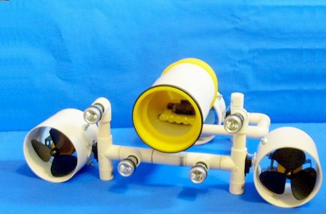
ABE design consist of three DC motors with special water proof. The control system uses a Fuzzy algorithm for underwater stability, sensed by an accelerometer. three underwater proof servos are used to move each thrusters for different movements. An illuminated system will be controlled by a light sensor, according to the ambient light. Other measures to consider are: temperature, pressure and water presence inside the bot, in this case will activated an special function to go back to the surface. In figure 1.1.1 its show the 3D model of ABE. The version 5 of ABE it is almost finished and under testing.


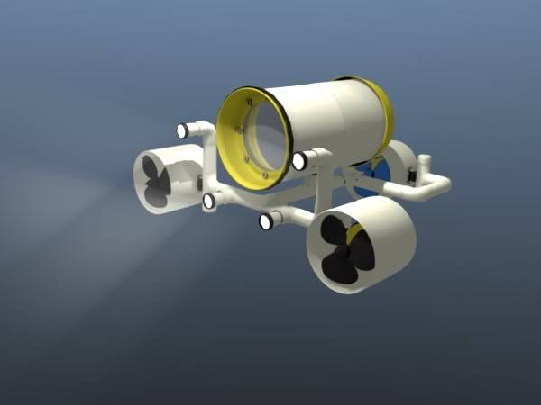
Fig. 1.1.1 - ABE 3D design.


In the Video shows the process of assembling ABE, this version uses a minimum of parts for ABE version 5.


2.1 Circuit Design


The circuits used in ABE are several boards divided in two main areas: control and sensing. Each board contains the basic circuits to move the bot and obtain vital information from the enviroment. This boards are conected to the XK-1 (Figure 2.1.1) The control board wich is used for the motors are in pins XD12 - XD23. The sensor and lighting control are in pins XD0 - XD11.


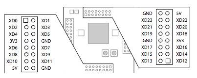
Fig. 2.1.1 - XK-1 pins locations to use for control and sensing boards.


All the boards are put together in cube arrangement that contains: main sensor board, control board, XK-1 and power board. This is ilustrated in figure 2.1.2.


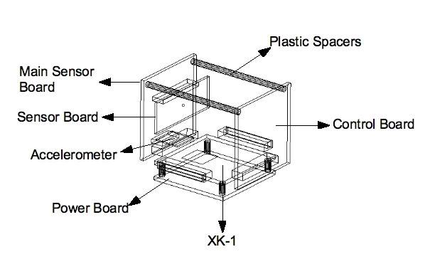
Fig. 2.1.2 - PCB Arragement for X-BOX.


Power Board - The PCB uses 7805, 7809 to obtain 5, 9 Volts,output reference voltages and a small DC-DC converter.

Sensor Board - This PCB uses a LM35 for temperature sensing, a basic water precense sensor and a small power circuit to activate the lighting system and an accelerometer for position control sensor.

Main Sensor Board - The main use of this board, its to obtain analog data from the sensor to the XK-1, according to x-linkers[*] ,there is available code for MCP3208 , this 12-bit SAR ADC from MicroChip has 8 input pins, multiplexed to a 100 ksps ADC. The board will use one of this IC, with an 4017 to multiplex ports to use for control purposes.

Control Board - This board will take the signals from the XK-1 to control 4 DC motors and up to 9 servos. To achive this task, its use an 74hc595 to send signals control for two L293D. Also, a 4017 will multiplex the signal for the servos.


3 Algorithms Design

3.1 Basic Servo Control

Soon ..


3.2 Basic PWM - DC Motor Control

Soon..


4 Simulation and Testing

4.1 - Trhuster Test

Soon ...


underwater exploration for lakes and reefs

  • Control method: Autonomous.
  • CPU: xk-1

This is a companion discussion topic for the original entry at https://community.robotshop.com/robots/show/project-abe-xmos-challenge

Great looking submarine.What
Great looking submarine.<o:p></o:p>What will you use to weight it down? Or will you use the thrusters to pull it under?

Have you got any more information on the thrusters and where you got them?

Like what geir mentioned

Like what geir mentioned this will deffinatly need to be weighted and balanced to give a neutral buyancy at depth.

I think there are some model submarine sites that have some great products to help in this along with monitoring depth, controling depth and any water leaks(emergency ballest dump if needed).

This looks pretty cool so far though, great work!

How cool. Autonomous under

How cool. Autonomous under water robot. Cool!

(I may not sound that intelligent, but it is what I have to say though :slight_smile:

>
hello Geir, Well, I was planning to pull it using the thrusters as first instance, in the model I considered several ways for submersion, all this in a very simple manner and the solution was using the thrusters: which I made using parts from different objects, I will post how I designed them, very soon.

-

There exist equilibrium , the system its balanced. Right now I’m seeing how to maintain the ABE model at certains depths, I design a few algorithms that I will summarize them within the weekend, I got a lot of material that I will share in the official site very soon.

Emergency ballest dump …Could u give a bit more info about it>?


ok
jeje… no problem fritsi… :slight_smile:

are u
going to post how you water proofed everything?

**i like **
i like the project by the way :stuck_out_tongue:

Emergency ballest dump…

Very simple. Basically, the unit floats, period. Weights are added to obtain nuetral boyancy. You should have the ability to drop these weights in case of emergency. You are looking for a fail-safe here, in that in the event of a failure of thrusters or brains or batteries etc. the result is dropping of the ballest and the unit floats to the surface. Something as simple as keeping a relay clicked during normal opperation so if a failure happens, the relay defaults to it’s normal position (unclicked) and drops the weights.


Hey good job. Balancing

Hey good job.

Balancing your sub you need to consider its use.

For example if you were to be flying just above the bottom you would want it light so as not to disturbe the seabed and mess up visibility. Though offshore ROV’s are usually heavy so not to lose the sub in the mid water high currents if the umbilical was parted.

yep yep, right on the money
yep yep, right on the money CTC!

Not sure if you’ve seen this

Not sure if you’ve seen this book but thought I’d throw it out there.

It’s a bit dated, but has ideas and experiments for building rovs. I have it in my library as I was going to build one a while back but never got to building one. :confused:

It may not be useful as you have quite a bit built, but I noted what appeared to be servos that would control the motor direction…not sure how welll that would work underwater…though I’m sure this is just a visual prototype :slight_smile:


ROV photos

Here are some pics that might inspire you.


The Canyon Quest made by Shiling Robotics

|x

Then the Perry XLS

|x


And lastly my favourit, the Saipem Innovator.

|x


=
ok, now I got a clear picture of the configuration.

-

I got a similar book that I downloaded from a torrent , a few Ideas I borrow to design ABE, this article is nice to study too.

Análisis Experimental de una Arquitectura Sensorial para un robot SubAquatico.
C. Espejo, M. Almonacid, R. Saltaren, J. Ibarrola, J. L. Coronado.
Universidad Politécnica de Cartagena. Universidad Politécnica de Madrid

-

Part of the waterproof concept its based on this nice tutorial from SoR…

http://www.societyofrobots.com/actuators_waterproof_servo.shtml

ep… I saw a few pics of

ep… I saw a few pics of ROVs, that’s a big one…

This are another inspirational link…

http://www.expresspcb.com/Feedback/ROV/ROV.htm

http://robotics.ee.uwa.edu.au/auv/usal.html

I’m making something small, the use of this model is for small areas like lakes.


Hey Again, Those big ones

Hey Again,

Those big ones is what I play with. If you want small try

AC ROV

Sea Botix (it also comes with wheels)

Sea Eye falcon

Sub Atlantic Mohican

These are to just name a few.


Cool
AC ROV rocks… so nice and small… º)