Introducing Penny. She's beginning her existence as a Start Here style robot. However, she's based on an Arduino Mega.
Video 1: Early testing of the servo and Sharp IR sensor used to test my code.
Video 2: Penny prototyped on a breadboard and running fine
Chassis
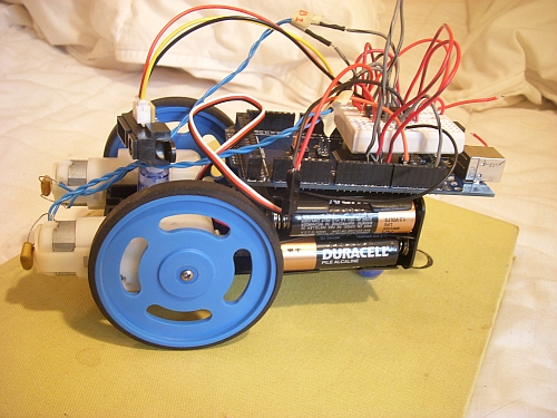
I re-used the motors, wheels and chassis from my original SHR, which has been gathering dust for a while.
Penny is configured back-to-front from the old SHR, with her drive wheels in the lead. I set the Sharp IR sensor back as far as practical, since it doesn't work well closer than 10 cm anyway.
The messy breadboard will get cleaned up. I plan to use Ro-Bot-X's Arduino shield for building robots, which will take care of .some of that wiring for me.
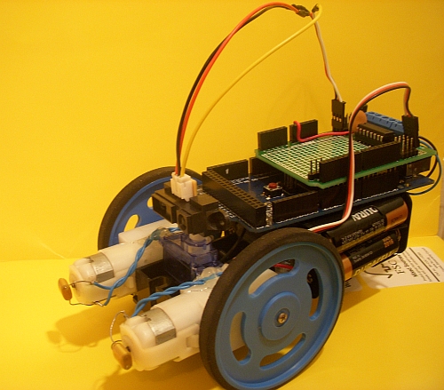
Update 2010-10-05: I have received the Ro-Bot-X designed Arduino shield and gave Penny an upgrade. Look at her now. Quite a difference!
Code
Penny 1.0 is based on a straight translation of fritls' Start Here code for the Picaxe. This is my first Arduino robot, so I wanted to start simple. I'm very pleased with the result.
I have attached the original code as well as an updated version that is fit for the Arduino shield and adds a backup function.
Electronics
I'm using an SN754410NE dual h-bridge motor driver. No other electronics yet.
Execution
As you can see in the 2nd video, Penny is working fine. I adjusted some parameters, like how far away she reacts to an obstacle. There's plenty of room for enhancement of the basic SHR code, and I'll use Penny as a platform for learning more about the Arduino.
Future
The future is bright for Penny. I have a lot of possible enhancements with an Arduino Mega as the brain power. We may see features like:
Wheel encoders
PWM
Line following
Edge/cliff detection
More actuators
Perhaps... penmanship
Actuators / output devices: 2 GM9 from Hobby Engineering with upgrade, DAGU mini servo
CPU: Arduino Mega
Power source: 4xAA alkaline batteries
Programming language: Arduino
Sensors / input devices: Sharp GP2Y0A21YK0F IR sensor
Target environment: Indoors. Carpet or smooth floors
On the duemilanove you would need to address the pin with it’s “pin number” when using pinMode and digitalWrite, while you would use a number from 0 to 5 (duemilanove has 6 analog inputs) when using the analogRead. I’ll explain myself better: let’s say you want to set the first adc pin as input and activate internal pull-ups, you would do something like this:
pinMode(14, OUTPUT);
digitalWrite(14, HIGH);
and to read from the SAME analog pin you’d write:
analogRead(0);
For pinMode and digitalWrite you gotta start counting from the first arduino pin, and analog ones come right after. For analogRead you start counting from 0, which represents the first pin. You may want to write it down in case you want to make an arduino-based SHR so that folks using duemilanoves can get it working :=)
ps: you probably know this much better than me…main purpose of my post was just reminding :=)
NICE example SHR! Great video explanation - something I need to do in my own videos…
I really ought to get an order in to Ro-Bot-X for his robo-shield. I seem to keep building the SN754410NE on a breadboad shield for a quick test project, then tear it down, then later end up building it all over again. Would probably spare me some wasted time and effort… :-/
Actually, since I’m totally new to the Arduino, it is an interesting point. I read that about the Duemilanove. When it came time to code, I figured out I would need to use pin 54 for my pinMode and digitalWrite commands to set the pullup high, just as you say. But why declare a second variable just so the pin matches the printing on the board?
Since I wasn’t used to this convention, I kept it simple and used the same variable storing ‘54’ for the analogRead command as well. It worked fine, but it is helpful to know that Arduino convention is as you describe it. Thanks for the education. ; j
Righto, so here seems a good place to ask a few questions that are bugging me (not about penny, s/he’s lovely).
You use a SN754410NE - in the case of penny, is there any difference between the functionality of an h-bridge, and of a L293 motordriver?
By using robot-x’s shield, you’ve cleaned up a lot of that wiring; I assume it’s possible to achieve a similar outcome if you customised a circuit board? So is it true that using robot-x’s board is a kind of multi-purpose re-wirer?
While I’m at it, what is the difference between “shield” and “board” in this context?
Now you have the arduino shield/board and RX’s shield on penny, does that mean it will ALWAYS be on penny (as long as she lives)? or do you intend to later cannibalise her for parts - specifically the arduino and RX’s shield/board? (I don’t have an arduino, and I’m not sure what they give that isn’t accessible from a picaxe, and they seem to be much less versatile-per-dollar. since you’ve done both - what’s your view?)
The SN754410NE is described as being pin for pin compatible with teh L293 driver. They are both h-bridges. The L293 includes internal clamp diodes, while I’ve heard that external clamp diodes are recommended for the SN754410NE (though I’m not using any).
Ro-Bot-X’s shield is just a custom board that happens to suit my needs. The term “shield” is an Arduino community term for a board that stacks onto an Arduino.
This is my first Arduino. I have futher plans for Penny, so she’s safe for now. We’ll see what happens in the future.
I have found the Aruino to be more flexible than the Picaxe, and pretty easy to learn. I’m playing with some navigation routines right now that require floating point math, which is something you can’t do on the Picaxe.
Yes, those caps are for reducing motor noise. You add 0.1 uF caps across the motor terminals. You can optionally add two more caps per motor. Each connects from one motor terminal to the metal case of the motor.