This is my first robot im attepting to build, I want it to do the basic things to start with such as to avoid obsticals and such.The base is made of some ply wood i found around my house, lego and two gearboxes i baught from my local electrical store.
The robot isnt to big but not to small either, I intend to add sonar and light resistors soon after getting my robots locomotion in order :).
The microcontroller it will be using is a Picaxe 28A basic board like the one found in the start here guide although mine cant have as much code. (I might upgrade to the X1 soon) :)
here is aditional pictures of my robot (Knowledge bot).
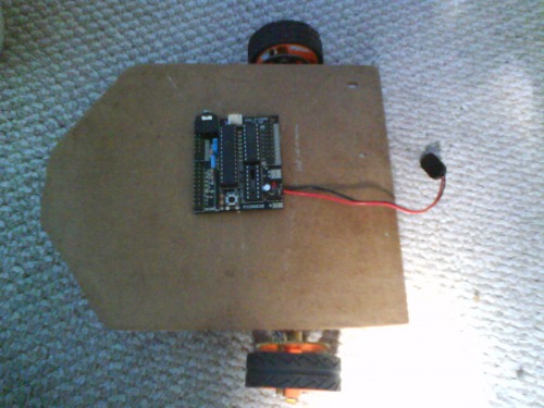
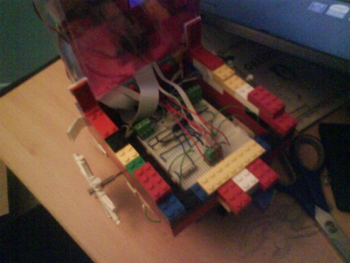
This is my robot so far shown from the top as you can see my microcontroler is just sitting ontop :).
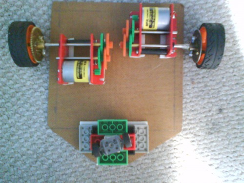
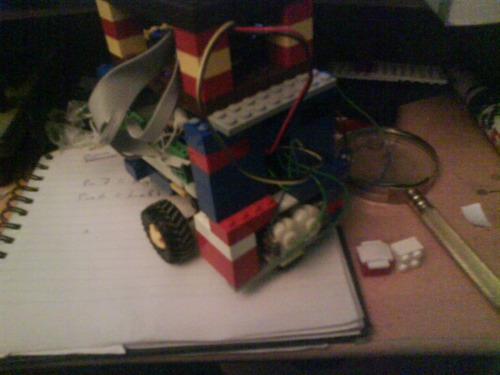
This is my robot form beneath it shows the lego wheels at the back (pointed bit) this is going to act as a caster.
As you can see its no made in lego, i done this because it is now alot stronger and easier to change. There is a front bummper wich will have two switches behind it so that when it hits somthing it can take evasive action!!!.
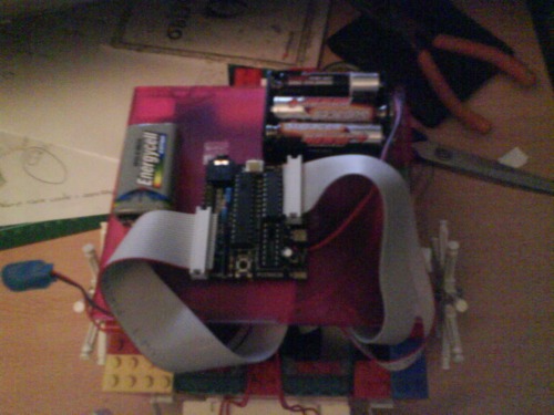
As you can see here is the top it is now useing two batterys a 9v and a 6v batery pack, the 9v is for the motors i have made a circuit on two bread boards that controll my motors with a motor controller.
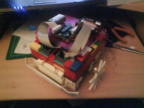
This is the two bread boreds connected inside the robot, as you can see i have used a CD case and used some hinges so i can acsess the insides easily.
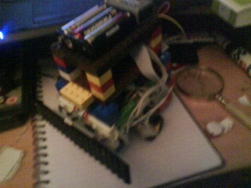
Compleatly had to remake this bot apart from the code (it was to heavy).
Here she is now :)
Here is another picture>>>
I will post a video shortly atm it is uploading so give me 10 min's =].
**i have a little ** I have a little and i learn fast :), I will take your advice and supper glue the lego together dont no why i didnt think of that THANKS :).
BTW i want to add my microcontroller and my motor controller to this project but im a little unshure on how to make it work or if it wud go boom. << i dont want that >>
The motors are 12-24v you see they do work with a 9v witch i would like to use as the secondary power for my servo once added and my motors. I have been told that if the motors stall it may cause a spike in the current inwitch will fry my motor controler what can i do about this ? ty
The caster needs to be on a The caster needs to be on a pin, dragged - or it will not turn. Take a look at a trolley in your local supermarket, how the wheel is not over the turning axle, but left behind to "drag in place"
He could just make it front He could just make it front wheel drive with teh caster behind it, all he would need to do is to turn it around. As for current spikes add 0.1uf capacitors on the motors. That helps remove nearly all spikes you would encounter.
oh why ty i actly have some capacitors on the motors they came pre solderd :), and as for the caster i no it looks strange but the caster is as the back and is going to be draged along what you think do you have any more ideas
**what you have said ** now i think about what you have said i think i will make that the front and putt a caster like roller on there or somthing but what should i use :S ?
I would have the caster on the back as it will improve the movement of your robot. I would now study some basic electronics. Go here so you can learn some more:
Thanks for the advice :). I have just changed the caster it a rounded sort of serface should i change the mosition of the gearboxes and the caster now so that the caster is at the back then ?. btw i dont mind its only stuck down with sticky fixers
I’d say leave the motors as I’d say leave the motors as they are, they look good on the current picture. I would now go to a hardware store and order a plethera of bolts, nuts, spacers, etc. Make sure they are all 4-40 size (because that is a common size for PCB mount holes). Get all sorts of lengths. As for spacers get some aluminum tubing that can fit the 4-40 bolts, or even nylon tubing.
okay … what will i need this for ? future projects ? sorry im not to bright somtimes :).
I think i mite chance it and wire up my microcontroler to my motor controller. although i dont no how to use it …
btw ill have to save up to get the bolts and that as i spent all of my money on the parts i have now is there a way you could help me gett my robot running maybe just ysing light sensors i have two of those
I think it’s great that you want to build a robot of your own design rather than copying someone else’s design. That’s definitely the right attitude. But the problem is that if you don’t know how this all works, then you end up asking everyone to “help” you with it, which basically means they’re still designing your robot for you.
I think it’d be a good idea for you to set this one aside and build the Start Here robot first. Sure, it’s not as fun as building your own, but you’ll learn a lot about how the PicAxe should be connected to the motors, what works and what doesn’t, etc. Then, with that knowledge, you can come back to this robot and finish it without having to ask for help at every step.
The other alternative is to do more research for yourself. Pretty much everything you want to know is already available online – you just have to go ask Google for it. Look up the datasheet for your motor controller to find out which pins need to be connected to what. I don’t have experience with PicAxe but I’m sure there’s documentation online explaining how to wire up the project board you’ve got.
It sounds like you’ve got a decent grasp of the basics – you know what a capacitor is, etc – so you can definitely find the answers to your questions yourself with a little Googling. People are always more willing to help when it sounds like you’ve tried to find the answers for yourself first.
Good luck with that robot, it looks like a good start.
thank you Thank you i do understand what your saying and yes im gunna copy his idea now thanks but im going to stay with this desighn as i have no money left. the only thing holding me back realy (he says with his picaxe book in hand) is that im worried im going to fry my chip haha and i no as you said the information is online and everything i have had a look and also in the book :).
Fritsl’s <START HERE> Guide involves soldering i cannot do this as i dont have a soldering iron and i cant use them >< hehe, so i have created this bread board as you can see this should work from the normal outputt pins now and i hope so im just trying to double check to see if i should putt any resistors or capasitors in there. (i have capasitors on my motors but i think thats to stop noise)
As you know from my private messages to you, I am not that polite, but the idea is the same. I will just add up: You are not going to build a robot without soldering at all. So chose; Face soldering or find another hobby
I dont mind being told for you lot no a hell of alot more than me Fritsl i am trying to build you start here robot tho just not the way you have… if it fails it fails lifes a … lol but it goes on for now im going to read my picaxe book and learn a bit more, im going to try and copy your start here robot as much as i can as it is a GRATE way to start and if i had a soldering iron and solder i would shurly build it just like you have thanks for the information.
oh and i want to learn to solder i do not give up but when i have a soldering iron prehaps for now its what i have, also what do you mean bby ADDing UP do u mean getting adgitated by me ? if so pm nicely n ill shup n move along but i dont think your like that as you all seem kool could you please explain tho as i may have taken this the wrong way compleatly.
Those motor/gearboxes looks sweet, where did you find’em? price, brand name, any other info?
You’ll have to excuse fritsl and the rest of us Scandies. We’re not rude. It’s just that the semi-arctic climate makes us speak loud and in short sentences. And that doesn’t make for delicate conversations or unnessecary niceties. But we love you just the same, I’m sure.
Thanx for adding that i should of gave a direct link
I have a question its buggin me ive been trying to firgure it out for hours now ¬¬, right i have this circuit shown below but the thing is the wires that go to the picaxe how do i no what wire is V2 and what wire is the pin number :S.
Would someone give me a link as ti find out more info about it or explain how i would no chears


 ty
ty although i dont no how to use it …
  the only thing holding me back realy (he says with his picaxe book in hand) is that im worried im going to fry my chip haha and i no as you said the information is online and everything i have had a look and also in the book :).