OFR (Object Following Robot)


I have been having this idea in my mind for awhile. Now I want to get it out and put it on the drawing board.

OFR is a robot that follows a specific infared siginal around and around where ever it goes!

I'll give updates on my progress


I have made an infared emmiter from some parts and it emmits a 38kHz. This will be what the robot will follow.


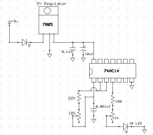
I have planned out the circut board that emmits a 38 kHz signal.


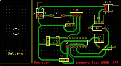
Also I have it designed in a PCB form.

The 7805 voltage regulator turn 9V to 5V enough for the chip to handle.

22k and the 10k varrible resistor helps the capacitor charge at different speeds.

The 74AC14 is an inverter chip.

th capacitor charges about 38,000 times per second and transfer it to the infared LED which generates a 38kHz signal


I'm waiting for my PICAXE kit to arrive.


in the meantime i'm having trouble solving how it's head is going to find, lock on, and follow the infared beam.

if anyone has an idea, feal free to tell me :)


Thanks to Chris the Carpenter, I decided to use the Pololu beacon transceiver.


I have recievied my PICAXE and instead of the pololu dual serial motor controller, I used the solarbotics L298 motor driver. I hooked it up to 2 motors and to the PICAXE. The PICAXE gives signals to the L298 motor driver and it drives themotors. Also indicating the direction through fashionable LEDs.=)


This is what I have so far.


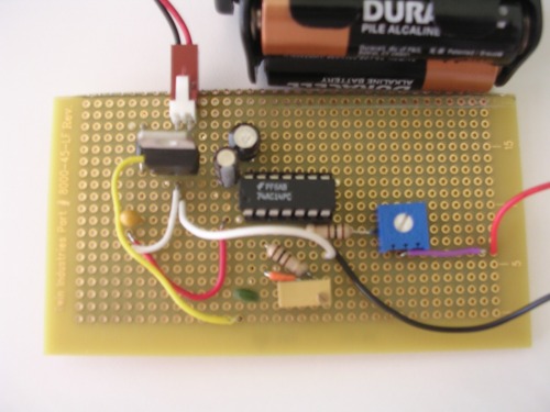
I just finished the emmiter circut on a perf board.


Close uo of the components:

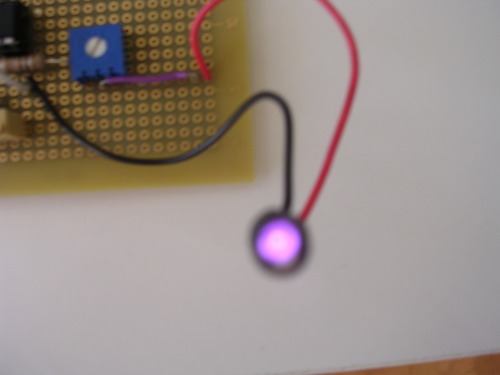
The Infared LED Looks great at 56kHz


I finally finished the robot after many program problems.


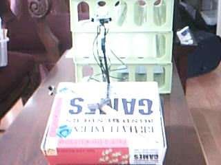
yes the body is a puzzle calender. I stumbled upon it and thought it was really good!

This is in the engine. The PICAXE is wired to the motor driver really badly. I couldn't find good connectors, usually the soder would break and the wire would come off.

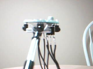
That is the Pololu Infared Beacon sitting at the top of some lego sticks.


Follow an Infared beam around

  • Actuators / output devices: 2 motors
  • Operating system: Picaxe 28x1
  • Power source: 4 AA batteries
  • Sensors / input devices: 56 Khz IR Detector
  • Target environment: indoor

This is a companion discussion topic for the original entry at https://community.robotshop.com/robots/show/ofr-object-following-robot

This quind of robots may be

This quind of robots may be very usefull, like for transport things, and so on… its always nice, and fun…


Good luck with your project, i will help with what i can.

Thanks

Thanks,

I’ll ask for help when I can.

Hey, you do know about these, right?

http://www.pololu.com/catalog/product/702

I’ve wanted to play with these for a while now.

www.rocketbrandcustom.com baby!!

You need a LOT more caps
You need a LOT more caps around the power supply (tantalum) to reduce false spikes. Make sure you use a mylar or silver mylar cap too.

Nice! BaseOverApex - This is
Nice! BaseOverApex - This is your sollution for the Big Chaser, no?

Thanks
Thanks, I’m still waiting for the sensor.

Not so sure

Looks like a PP3. I can’t see a need for caps on the input side of the regulator unless you’re using the 9V to drive something else as well. You’ve already got some buffer juice and looks like a bit of decoupleing, too on the output.

Where would you stick extra caps? I ask because power supplies are alwasy causing havoc in my bots!!

Erm.
I’m thinking “yes.”

Whopper-size it

How about two IR phototransistors? There’d be a bit of a trick getting them to react only to 38KHz, but it could be done. Point the in slightly different directions and establish which is the strongest…

Do you mean instead of using

Do you mean instead of using 38kHz sensors use IR phototransistors?

How about an infared photodiode?

Errrm.
I issed the bit where you aid you had 38kHz sensors. Use 38kHz sensors if you have 'em .

Nice Job!

Man, I just love seeing neat, clean homemade boards --Great Job. Boy do I want to see this one work… well, I just want to steal the idea!

-One thought, if the IR LED was put into a little tube where it could only shoot one direction -or- the IR sensor had “blinders” in the same fashon could this take care of any false or vauge readings? I’m just brainstorming.

www.rocketbrandcustom.com baby!!

that’s very interesting! how
that’s very interesting! how did you make your calculations to know you would exactly get a 38 kHz signal?

Nice, you wouldn’t happen to

Nice, you wouldn’t happen to have read “Intermediate Robot Building” by David Cook, would you? That emitter circuit looks just like the one David does in his book. :slight_smile:

Although this emitter circuit is definitely working, it takes a bit of adjusting the trimpot to get it close to 38KHz. An easier way would be to drive the 38KHz signal directly from a PWM-pin on a microcontroller. This way you can easily get it very close to 38KHz.

Is that ExpressPCB you’re using for designing?

Keep up the good work!

- Jimmy

Yes and Yes. Have you read
Yes and Yes. Have you read that book too. It was really good.

Yeah I’ve read it too and

Yeah I’ve read it too and thought it was really good too :-). Amazing how much you learn from reading his two books “Robot Building for Beginners” and “Intermediate Robot Building”. I recommend them to everyone!

Regarding ExpressPCB I think you’d be better off using the standard symbols for components instead of copying David’s beginner-friendly way of showing components. Generally a schematic should not be coupled to specific packages of components (for instance you’re using a TO220 package for you voltage regulator in your schematic and a 14-pin DIP for the inverters) - this coupling should only be done when laying out the PCB. ExpressPCB already has lots of built in symbols for all the components you use in your schematic. If you adhere to standards it will make it easier for others to read and help out with problems and so on :slight_smile:

Well when you are sending
Well when you are sending 38k pulses you are going to be generating some spikes on the voltage line, not to mention the spikes from the motors will generate false inputs on the sensors, even if they arent touching! You need more caps :slight_smile:

Hey - .BMP does not scale as
Hey - .BMP does not scale as they should, would be cool if you’d use another format. Thanks :slight_smile:

picture position

You’ve posted the adress to the pictures on your harddrive. So nobody outside your house can see those pictures.

Try uploading them to an online picture service like Flickr or Picasa, then we can all see.

/ vzz-clck-“Maneuver”