New to robotics, attempting to build an obstacle avoidance robot, looking for some guidance

Updated post with new parts, ideas, pictures, and questions

Hello robotics community! This is my first post I have made here. Im fairy new to robotics and am looking for some guidance. Im looking to build a object avoidance robot but in all honestly I am lost. I am hoping to show you the parts that I currently have with hope that some of you will tell me how to put this robot together. 

I did model flight for 6 years before this. I've flown everything from collective pitch sport helicopters to glow fuel large scale aircraft. Robotics seems like something new and interesting. The possibilites with robotics seems unlimited, its exiting! (also cheaper, hehe)

Here are the parts that I have right now and some details that I know/noticed about them from either packing, research or past knowledge


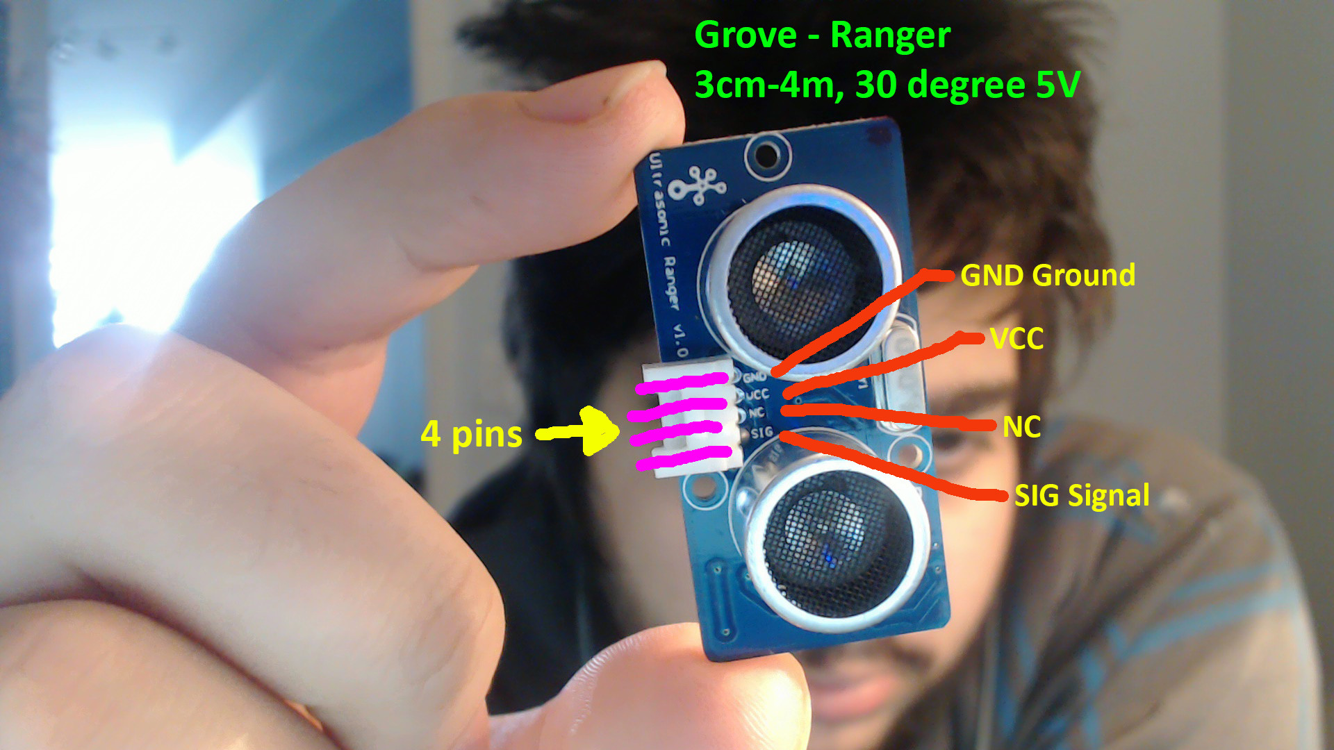
Ulrasonic Sensor

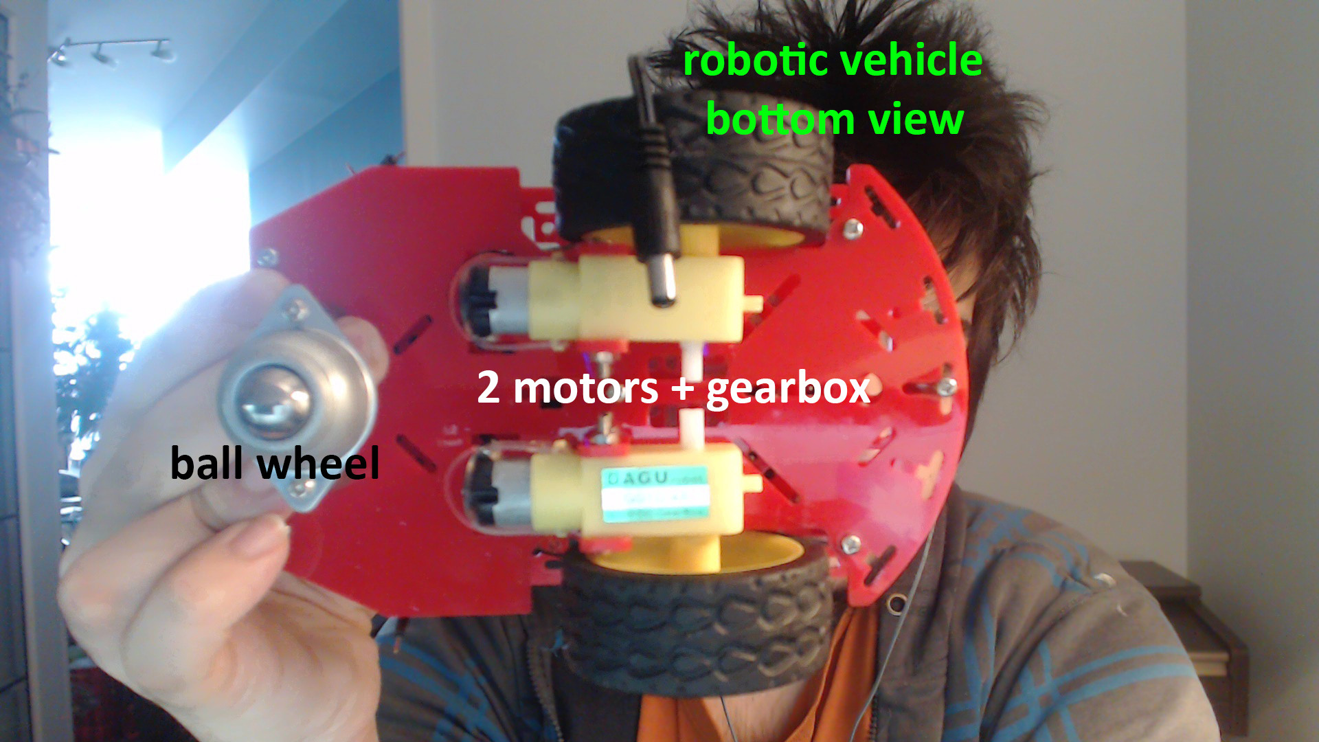
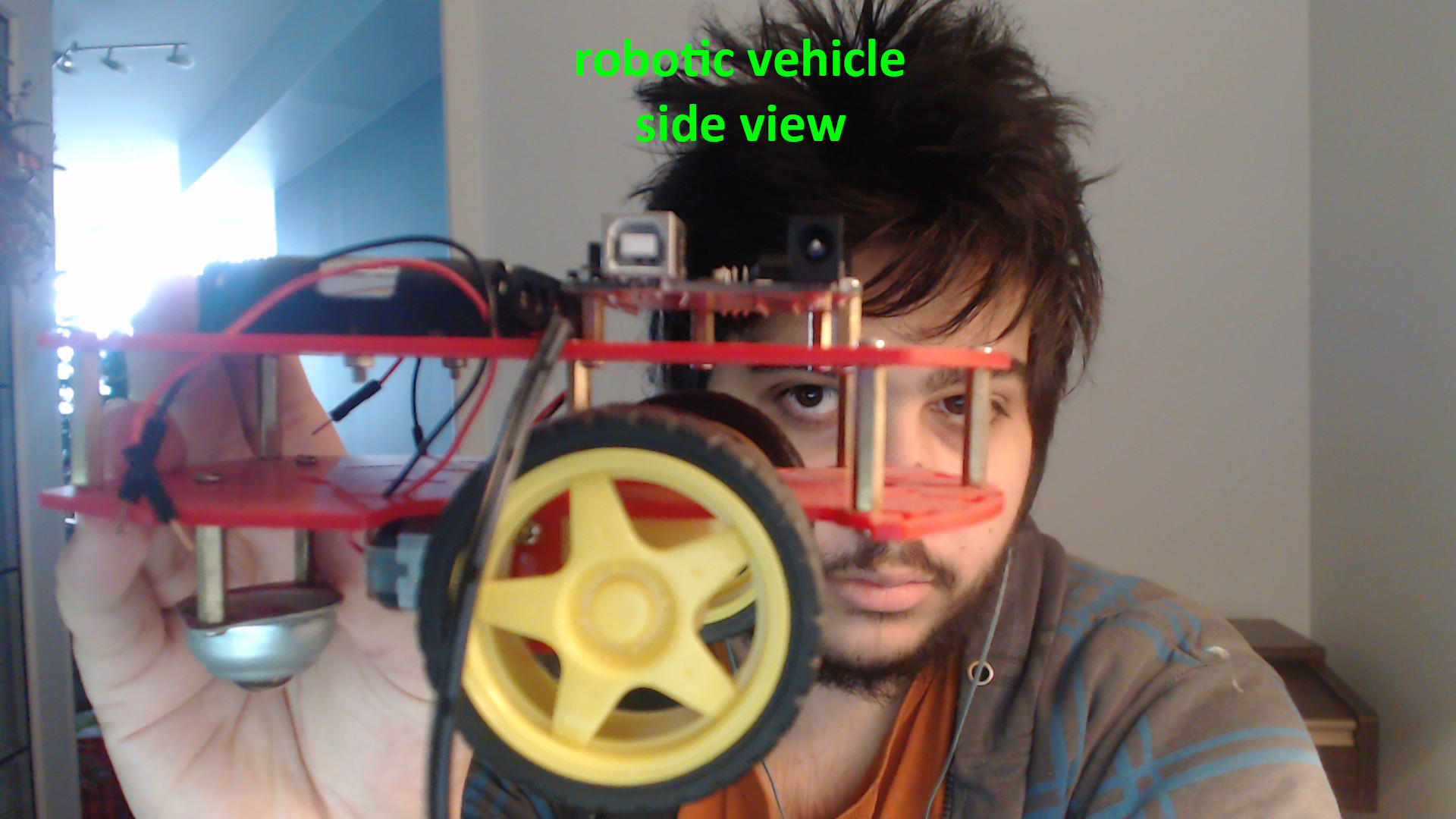
Robotic car kit (comes with body, wheels, 2 gear box motors, 1 metal ball wheel)

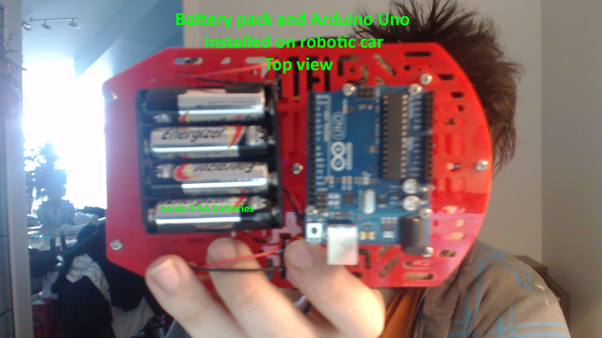
Arduino Uno & 4 x AA battery pack


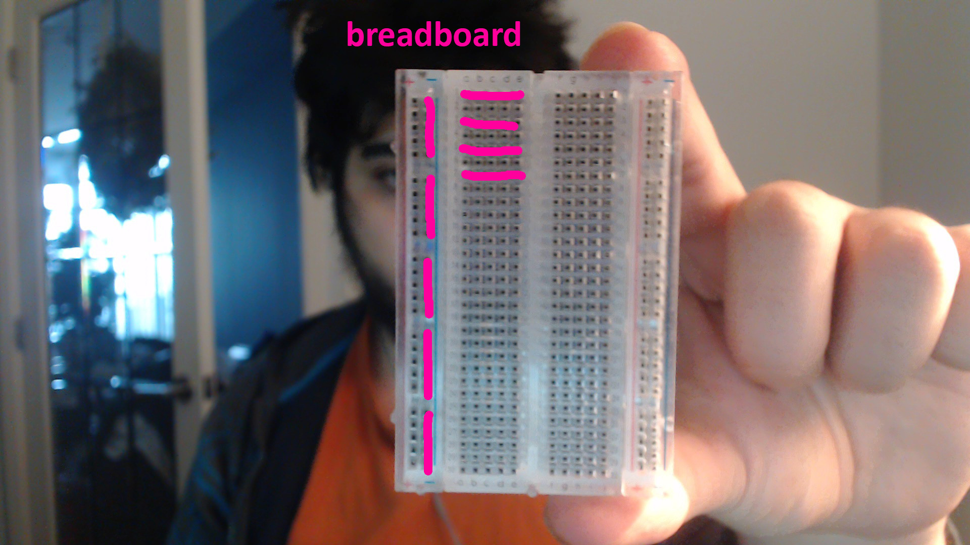
Breadboard

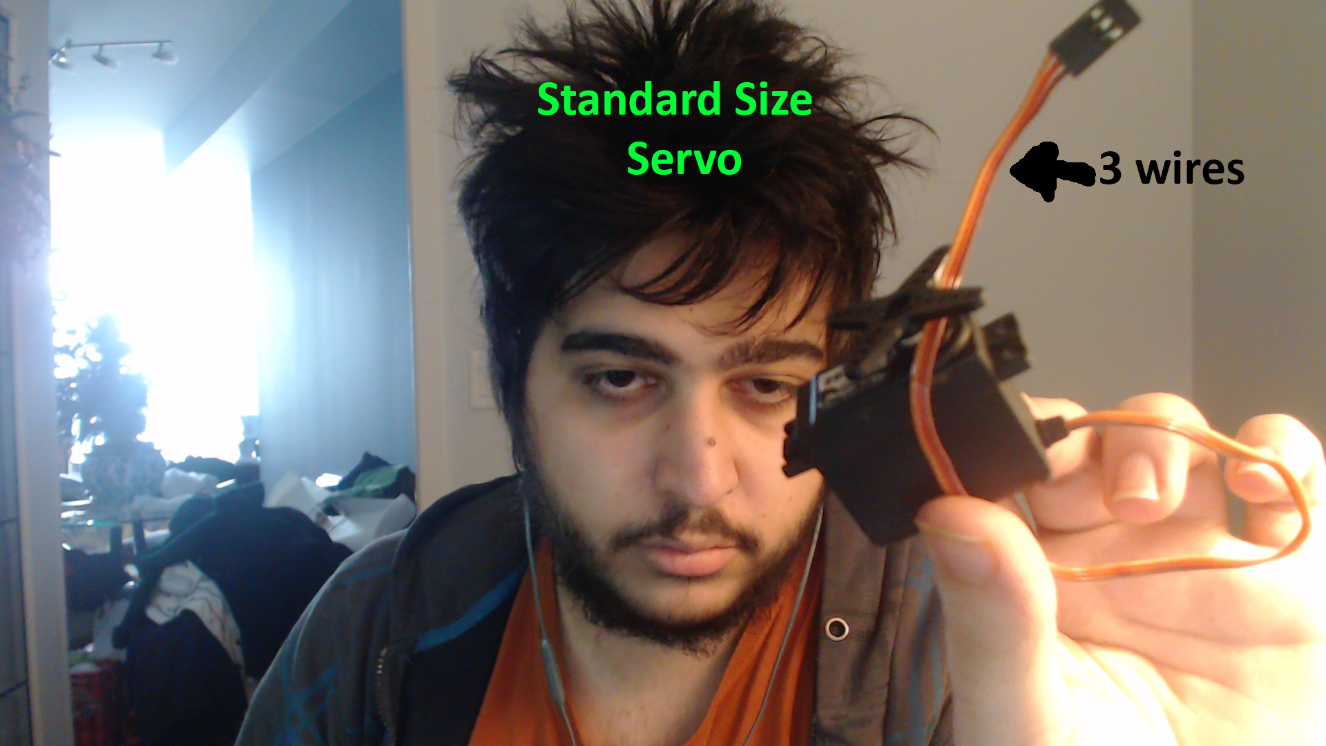
Servo


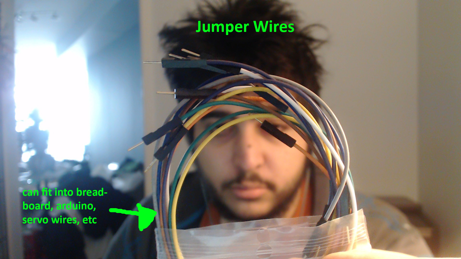
Jumper Wires


My main problem is the fact that I have zero idea of how to put it all together. I don't know what wires go where, what connects to what. I understand some of that changes depending on the code and what pins you choose to select as outputs, but generally Im clueless. I've looked for online guides but most of the guides use ultrasonic sensors with 3 pins, and some of the pins are labeled differently. 

If someone could help me out I would be so greatful. Im pretty sure I have everything I need, I just need the knowledge now. 

New Update #1

Most parts are attached where they should be.

Going to go out and get an H Bridge in a few hours, doing my best to keep the breadboard wiring clean since I know wiring the H Bridge is going to take some space.

Right now it can detect things in front of it and choose a direction. I hope to get the motors working so it can move and hope to get some LEDs to shine like car lights when turning and moving. 

Here is what it looks like, used some photoshop to make the colours(Canadian) look better since my phone camera is bad and it was a cloudy day.

New Update #2

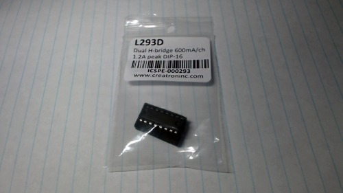
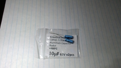
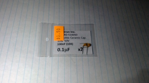
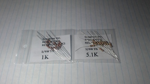
Visted a local electronics store and picked up these items for this robot.


L293D Dual H-bridge 600mA
10 µF 63V capacitor
0.1µF/100nF 50V capacitor
1k & 5k resistor
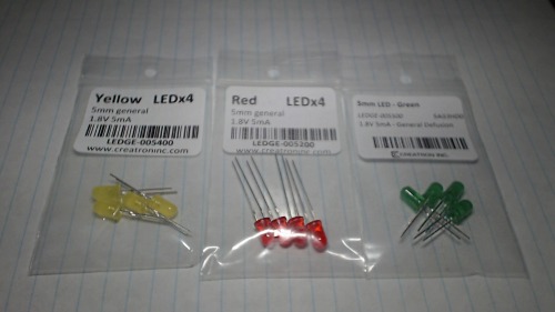
Yellow, Red, Green LEDs 1.8V 5mA
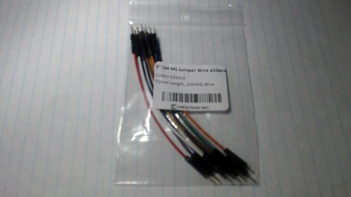
3" jumper wires
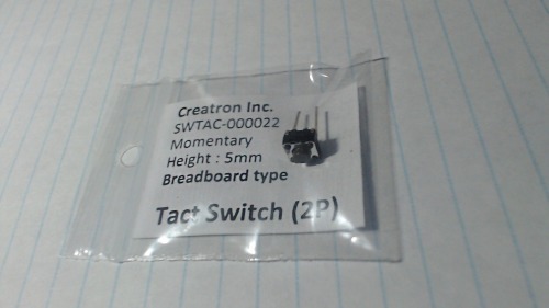
Switch 2pins
 

With these new parts I hope to complete the robot.


Future ideas.

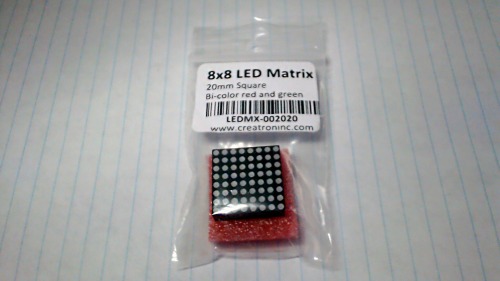
I also picked up this 8x8 LED matrix. I thought I could add this to the robot and display the distance to the wall in front of it as it moves. Maybe even add an arrow. It is a bi-color matrix with red and green, but red + green = yellow so I think I can have 3 colors.
Question

I purchased these items (everything from L293D to the 8x8 matrix) for just under $20. I just wanted to know if these prices are normal. Do the stores you buy from cost less? More? I myself was very happy with these prices. Im used to paying nearly $100 for an ESC, lipo and 1300kv brushless motor.


UPDATE 3


It has been tough figuring out how the L293D works, but I think I have the basics down.

Here is a picture of the wiring for Power
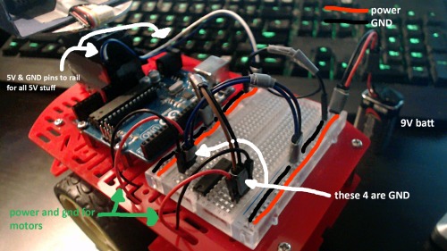
The 9v battery being plugged into the rail on the right side.

The 5v and GND pins are plugged into the rail on the left side. There is a black wire (with a loop) connecting the GND of the 9v rail on the right to the 5v rail on the left. 


Now for the L293D.

The 4 GND pins in the middle have been plugged in. The left side of the L293D is plugged into the 9v GND rail and the left side has been plugged into the 5v GND rail.

(As far as I can tell it makes no difference the position of the wires, as long as they are plugged into GND, that is why the GND are plugged in different places, because I want the wiring to be clean, and having them all in one place would force the wires into awkward non-natural positions)

The motor wires are plugged into their output slots. 

Next will probably be the rest of the wiring, hopefully It can be as clean as this. (imo this is clean, idk about ya'll)


UPDATE 4

Got new parts to hopefully finish the robot. Also got parts that I hope to add to the robot in the future.

Here they are. They were a bit pricy ($70) but Im confident I can use these parts for many things in the future, a good investment imo.
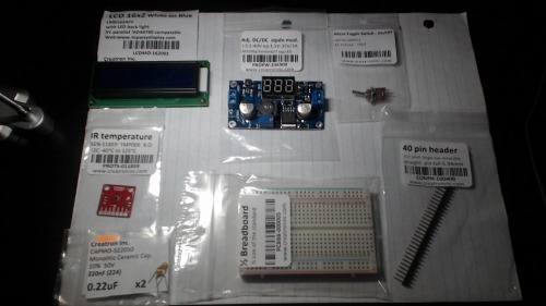
Hopefully my next update will be the robot working.

Any updates after that will be upgrades like IR heat sensor to locate flames and hopefully put them out :D


UPDATE 5

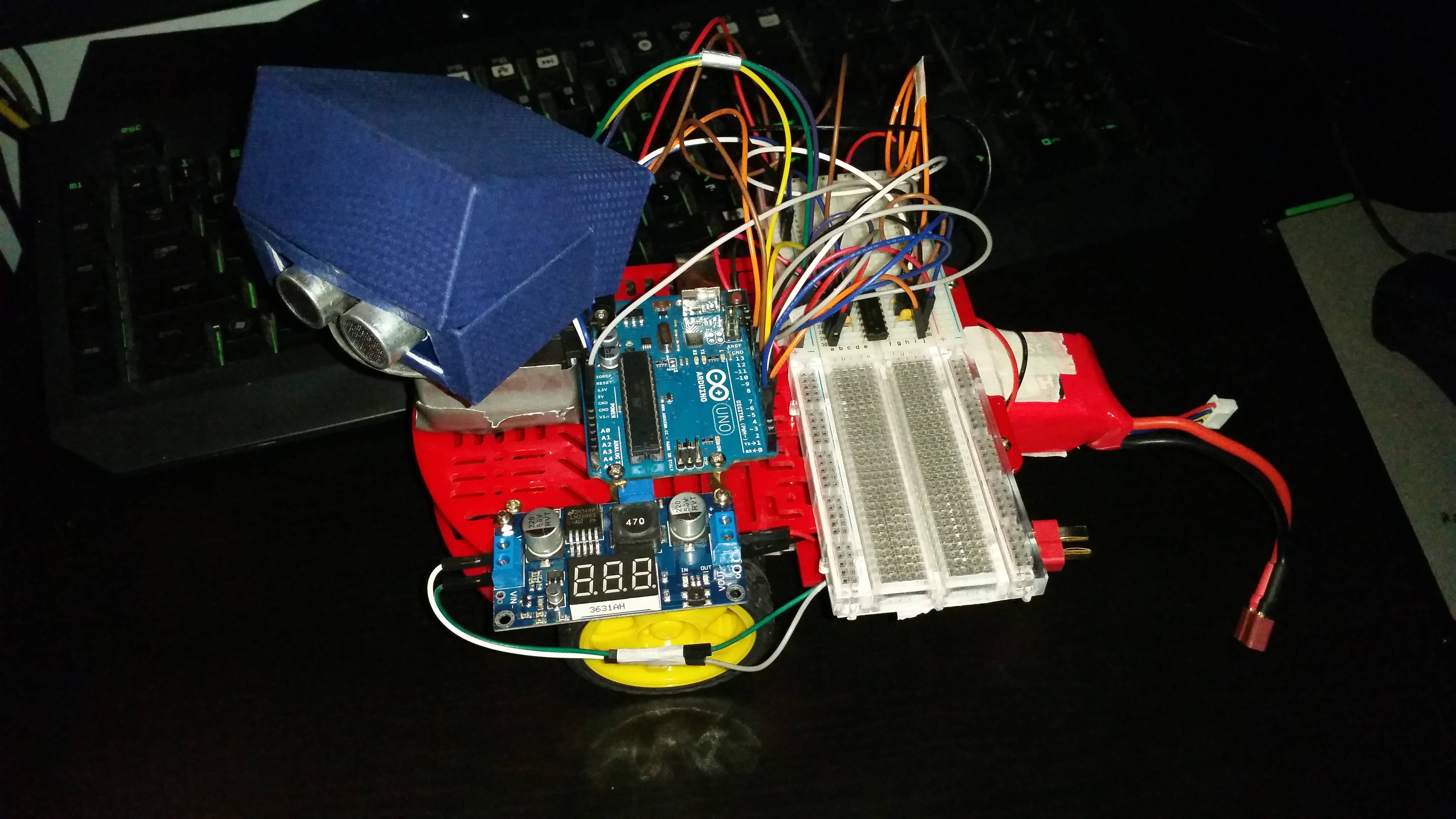
The first completed version of the robot has been completed. The algorithm is crude but gernally effective. I hope to add new updates with better built aglorithms that compenstate for non-perpendicular angles of attack into objects and pwm to change speed depending on distance. 

The video can be seen here, or at the top of this post where the videos are embedded. 

https://www.youtube.com/watch?v=69WIRMbgllA

This is a picture of the robot.


Obstacle avoidance using ultrasound sensor


This is a companion discussion topic for the original entry at https://community.robotshop.com/robots/show/new-to-robotics-attempting-to-build-an-obstacle-avoidance-robot-looking-for-some-guidance

Hey I used to own that

Hey I used to own that chassis. I named him pete and he was an obstacle avoider. Then he broke and I suppose that was my fault but anyways. If your looking for a tutorials on programming or electronics for the robot look here.

PING

SERVO

ELECTRONICS

good luck and tell me how it goes.

A few more pointers.

If you aren’t confident in your programming abilities, you may want to try some simple arduino tutorials to get a feel for writing software as well as understanding interaction between the microcontroller(arduino) and the outside world.

Your servo has 3 wires. They typically follow a standard color scheme where black is ground, red is power, and, white or in your case yellow is signal. Since servos contain motors they can pull a fair bit of current, at startup or if they are stressed. They sometimes require separate power, or, a capacitor to make sure they don’t cause the microcontroller to brownout(reset due to low voltage).

The power rails on your breadboard, labeled with the red and blue stripes, are actually connected together all the way from top to bottom. If you do not use dual powersupplies (typically 3.3v and 5v), you can actually tie the left and right sides together by running a jumper from the red rail on one side to the red rail on the other, and, the same can be done with the blue rail. There are larger breadboards that have a break in the power rails at the center. Your board is not one of those.

Your ultrasonic sensor will probably be very easy to control either through code you write to get data from it, or, by using a library like NewPing. I can not be absolutely sure because I do not recognize the brand.

Also, like Duane mentioned you will need a motor driver. L293, SN754410, L298(not preferred due to high voltage drop), L9110. You may consider tying the two inputs together with a NOT gate while sending a PWM signal to the ENABLE input. I would default to paying attention to what OddBot has to say over my suggestions any day. :slight_smile:

Finally, you may want to consider writing a program to control each component individually to see how things work. Once your code works independently you can start combining them to build up interactivity.

Some progress and problems

Since my post I’ve started trying to figure out how my ultrasonic sensor works. 

I began with finding out what the four pins all did and how to wire them up. Using google I came to this conclusion.

GND is ground and I connect that to GND on my Arduino

VCC is power/5 volts and I connect that to 5V on my Arduino

SIG is signal/trigger and it can connect to the pin I choose in my code. (it sends the command to make the ultrasonic ping)

NC is bounce/echo and it also connets to the pin I choose in my code. (it returns the signal back to the Arduino)


I looked for some online tutorials on 4 ping ultrasonic sensors and 90% of them were for HC-SR04. I copied the code and copied the wiring directions. Uploaded the code and opened the serial monitor. Unfortunetly I got 0cm, 0cm, repeating. I looked for an online guide showing how to fix this issue and I found this guide : http://www.instructables.com/id/Ultrasonic-Range-detector-using-Arduino-and-the-SR/

I downloaded the NewPing library and placed it into my library folder in arduino. Following the guides instructions I used the ‘NewPingExmaple’ code and it worked like a charm. 

I would rather prefer the code to work without a special newping library. The code I had from one of the guides I had looked at earlier was much more straightfoward. 

Here is the code from a guide that gave me 0cm results

#define trigPin 3

#define echoPin 2


void setup()

{

  Serial.begin (9600);

  pinMode(trigPin, OUTPUT);

  pinMode(echoPin, INPUT);

}

void loop(){

  int duration, distance;

  digitalWrite(trigPin, HIGH);

  delayMicroseconds(1000);

  digitalWrite(trigPin, LOW);

  duration = pulseIn(echoPin, HIGH);

  distance = (duration/2) /29.1;

  Serial.print(distance);

  Serial.println(" cm");

  delay(500);  

}

Here is the code from the NewPing download that works like a charm

// ---------------------------------------------------------------------------

// Example NewPing library sketch that does a ping about 20 times per second.

// ---------------------------------------------------------------------------


#include <NewPing.h>


#define trigPin 3  // Arduino pin tied to trigger pin on the ultrasonic sensor.

#define echoPin 2  // Arduino pin tied to echo pin on the ultrasonic sensor.

#define maxDistance 200 // Maximum distance we want to ping for (in centimeters). Maximum sensor distance is rated at 400-500cm.


NewPing sonar(trigPin, echoPin, maxDistance); // NewPing setup of pins and maximum distance.


void setup() {

  Serial.begin(9600); // Open serial monitor at 115200 baud to see ping results.

}


void loop() {

  delay(1000);                      // Wait 50ms between pings (about 20 pings/sec). 29ms should be the shortest delay between pings.

  unsigned int uS = sonar.ping(); // Send ping, get ping time in microseconds (uS).

  Serial.print(“Ping Result: “);

  Serial.print(uS / US_ROUNDTRIP_CM); // Convert ping time to distance in cm and print result (0 = outside set distance range)

  Serial.println(” cm”);

}


Another problem I face is that fact that it seems like I Must have a motor driver or H-bridge. I looked up some online guides to see if I can make one myself since the store I bought these parts from is pretty far away. I found a guide for it, will this work? http://www.instructables.com/id/How-to-make-an-H-bridge/

Im also interested in this NOT gate. Is it easier to build? Is it as effective? 


Im going to go at this slowly, step by step. 


Looking at your two programs

I notice you store the duration in the “no Lib” program in an INT. In the NewPing program it is stored in an unsigned INT. Google recently ran in to an issue with the variable that held the number of video views. It was originally an INT(?) that could hold up to 2+ billion views. If they had declared it as an unsigned INT, it could have held nearly twice as many counts. There are some downsides that have been discussed. Suffice it to say they decided to declare it as a 64 bit INT that can hold something like 9+ trillion views. Long story short, part of your issue is your signed INT can not hold a sufficiently large number for your duration. You could try declaring the duration variable as a LONG.

Regarding the use of libraries (libs), you may consider learning to make use of them as you will probably run across other hardware that you would like to try that has ready made libs. Not having to “reinvent the wheel” is nice when you are really just hacking around to see how stuff works. If you find you are running out of code space, you can always attempt to write your own code that only does specifically what you need without all the additions.

A NOT gate is a logic gate that when fed a HIGH will output a LOW or vice versa. It will not drive a motor. It is used to save the number of pins required to drive a motor. A couple of links to look at:
https://www.robotshop.com/letsmakerobots/node/32462
https://www.robotshop.com/letsmakerobots/h-bridge-motor-driver 

NC stands normally for Not

NC stands normally for Not Connected. It seems the Grove Ping uses only the SIG pin for communication. That also explains why the code does not work. Leave the NC pin unconnected and use this code for testing: http://arduino.cc/en/Tutorial/Ping?from=Tutorial.UltrasoundSensor


Thanks!

That worked. I actually had the same piece of code you just sent me an hour before you replied to me. It worked but I had no idea why it was working (and I need to know how or else else can I learn). I began stripping parts of the code out to see what it would and would not work without. Eventually I removed echo and anything related to it and it worked without it. Not long after you tell me to ignore echo and just use 3 pins. Such an interesting coincidense. I will further strip the code as much as I can while keeping it functional to get a skeleton copy of it, hopefully I can learn the basics of ping from it. 

After that I just need to either aquire an h-bridge (or make one myself) and I should have all the major roadblocks out of my way.

So many little details and problems that go with building what at first sight looks like a simple robot.

Great fun.

Before moving to h-bridge

Before moving to h-bridge you should review the NewPing library sketch as well. Lot of mistakes at your comments like

Serial.begin(9600); // Open serial monitor at 115200 9600 bits per second (baud) to see ping results

delay(1000); // Wait 50 1000 ms = 1 s, but why freeze everything for one second?

distance = (duration/2) /29.1; // Bad math to divide an int by a float and let the microcontroller do two divisions instead of one, duration/58 is ok using modulo rest classes at the moment

and so on…


Thanks, it was messy.

I’ve since reworked the code and have added some servo panning to the code as well. Scanning two sides and choosing the side with most distance. Since I dont have this h bridge yet (going to go and get one this afternoon) Im just putting a simple led in place of the motor in the code, using pin 13 led on the arduino for that.

Do you know a link to a guide where I can learn how to impliment this https://www.creatroninc.com/product/l293d-dual-h-bridge-driver-600ma/?search_query=L293D+&results=2 into my arduino robot?


There are at least 2 links in 2 replies.

I would imagine the link for OddBot’s write up talks about a generic h bridge and I know for sure one of the links I posted in one of my replies talks specifically about the '293 or the 754410 (they are pin compatible). As for code, any bot that drives a pair of motors (not continuous rotation servos) can be easily adapted for your needs.

I have a bit of code on pastebin that you should be able to use. http://pastebin.com/EXGjMNrz

I hope my reply is useful.

I forgot to mention. My code is based on one pin for direction and one for speed. Hopefully the comments are useful.

H-bridge

I’ve used that chip or it’s younger brother many times.

A nice tutorial can be found at Adafruit.

I think the best suggestion would be to learn the Arduino first. Turn LEDs on and off, use switches, etc. Then do the same things with your robot.

One great book you should have is “The Robot Builder’s Bonanza.”

Welcome to LMR and robotics
Welcome to LMR and robotics in general!

Read many guides, overall confused, but I have made progress

I used the guides you and some other sent me and found many different ways of connecting the H-Bridge L293D. Some have capacitors, resistors some don’t, some only have 1 of them, etc. 

Confusing.

But by reading them all and using this https://www.youtube.com/watch?v=5nDaHJqruq0 video I was able to understand the basics of it. 

Now there are many interesting variables that go with hooking it all up. All of the guides that have an external battery around 7V or up (usually 9V batteries but I saw some 12V stuff) use several capacitors and resistors. I imagine this is because they aren’t using the Arduino 5V line to power the L293D. 

However, I am only using the GND and 5V pins on the Arduino to power the entire project with the 4 AA batteries (6V total) plugged into the Arduino. To be honest all these different methods has confused on whether or not I need resistors or capacitors since Im only using the 5V pin from my Arduino and this L293D takes 5V to 36V. 

Also I have found that there are two main ways to plug the 4 outer pins (1, 8, 9, 16 on this http://luckylarry.co.uk/wp-content/uploads/2009/07/L293D.gif)

It has been 30 seconds since the last sentence I typed and I had an epiphany. Is pin 8 and pin 16 (Vs VSS aka positive negative) on this diagram the only pins you use for power? Because I just remembered several guides used pin 1 and 16 to control motor speed or something. 

As you can see I am pretty confused, lots of information out there, dont know what to believe.

So this is something very important I wanted to ask you more than anything.  Here is some code that I am using right now, some parts of the code I have //commented out because Im trying to figure out how it all works, I just dont want to delete it in case I need it. 

The code is canibalized from many different sources and I’ve made some small changes. Its sort of like frankenstein if you get my analogy.  Here is a link to the code: http://pastebin.com/LFDB4SJu

Basically this code makes the robot go forward until it gets 10cm or closer to an object and it stops. 

THE CATCH. It works yes, but the Robot makes a squeeky noice and the motors dont seem to have the torque to spin when I have them placed on level ground. This is wierd because if I use simpler code like this it works fine without a wierd squeek noise or lack of torque. Here is the code: http://pastebin.com/Nb1mvYkp

Hey what have you accomplished so far?

Very cool. Is there a chance you can give us a video? I would love to see that and what you have done so far a little better?