

Hello all,
YAYDM, Yet another Yellow Drum Machine!
I have gone away from the original a little bit, my one uses the Tamyia dual gear box and tracks, everything else is machined from Al. It is powered by 6 NiCads and I am using an Ardunio for the brains. I am working on the Sonar now, the drum sticks will be similar to the original but I am using Carbon Fibre rod (because I had some!).
The suspension is torsion bar and it looks cool running across the work bench over the screw drivers and pliers!
All the best
Cliff
//27Jan09
Thanks for all the Comments, Yes it is not yellow (at the moment) I will put some Video up soon. I decided to build a YDM because I came across a video of the original on UTube, it was the most entertaining thing I had seen in a long time! Very clever with a great deal of imagination. If people are interested I will tidy up the drawings and post them too.
A little more detail on mine.
The sides are machined from 6mm Al plate, the wheels are turned from 50mm Al Bar and have Brass bushes inserted.
The final drive is uses ball bearings from RC cars as does the Idler wheels.
The suspension consists of swing arms with steel axles which pivot in brass bushes which are "Locktighted" in to the side plates. The Torsion bars are 1mm Music Wire silver soldered to Brass bolts which bolt on the opposite Hull side plate.
I am building the Sonar at the moment, I cannot make up my mind if I am going to use a PIC to control the transducers or just drive it from the Ardunio.
I am using the same motors for the Drum Sticks as the original.
//28 Jan 09
I added a video, enjoy
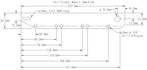
Well it's been awhile, lots on to keep me out of the workshop; anyway I promissed to put some details up and here is the beginning of them, just in case someone wanted to build the same chassis.
This is the hull, it is a 6 mm thick peice of Alum, I used dural of unknown parentage, you need two, I used 6mm to make it thick enough to tap, I milled out two pockets on the inside to reduce the weight but this is not really required, the slot at the front allows the track to be tensioned and the 10.9 mm hole at the rear takes the final drive shafts.
Next comes the main wheels:
These are a simple turning operation from Alum, just put a small radious on the rims, the Tamiya tracks will feed better. Make 6, now Alum is a poor metal for bearing so I pressed brass bushes into the centers, the bush is drawn here:
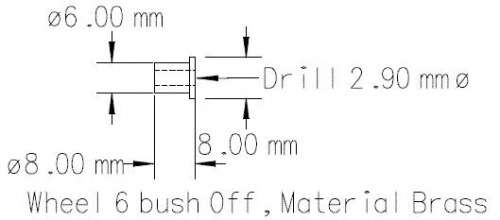
These are also simple turning exercises, I made a "D" bit to do the final boreing of the centers to get the best surface finish.
The Idler wheels are in the diagram below (right), the Idler is turned out of Alum, it runs on two ball bearings, I use the ones for RC cars, the hole in the middle of the wheel (9mm) is bored to fit the ball bearing, a small ridge is left in the middle to stop the bearing pushing through. The Axle (left) is turned from mild steel, I used 10mm hex bar, the ends (hatched) are tapped M4, I made brass nuts to suit. You need two of each.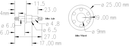
These drawings are the start of the suspension componets, in this case the swing arms:
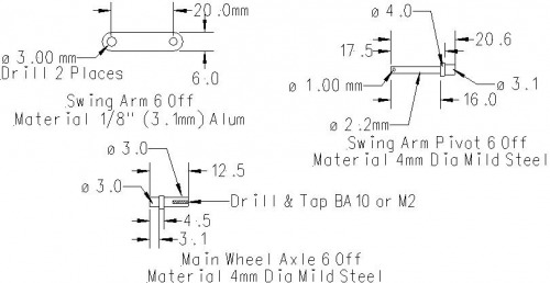
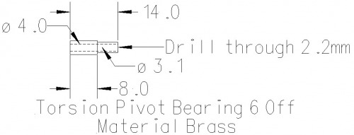
The swing arms are fairly simple, the Swing Arm Pivot is pressed/loctited in from one side and the Main wheel Axle from the other side. The finish on the Pivot and Axle is important, the bearing surfaces should be polished and and a close running fit in the wheel bush and the pivot bush (drawing below).
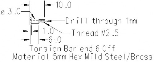
The following is the torsion bar end, this is silver soldered to a 0.8mm Spring(Music/Piano) Wire Torsion bar.
This is what the Swing Arms look like assembled.

The Torsion Bar is made with a small Z bent or C in the end, the length of the bar is set from the job, the length such the Torsion Bar end hard against the hull as shown and the torsion bar retains the swing arm, it should be such that a small amount of play being allowed. The ride hight is set by turning the Torsion Bar end and then it is locked in place using the Torsion Bar lock nut, this allows the preload to be set. If the suspension is too soft 1.0mm Music Wire can be subsituted.
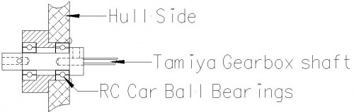
Final Drives! The gearbox I used is the Tamiya dual motor gearbox, the final drives are carried on two RC Car ball bearings each side. The bearing carriers are made like so:
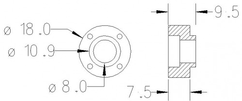
A simple turning operation in any metal (make 2), I used brass just because I had some. The 10.9mm hole should be turned a push fit on the bearings you get and the depth to suit the width of the bearing in my case 4mm, the step on the inside should be deep enought to hold the inner bearing in place, the for holes are tapped M2 or similar.

The final drive shafts (2) were turned from mild steel, the axle hole on the inside is drilled to clear the Tamiya Axles, the M2 on top serve to trap the axle. the M2 at the other end (left) holds the Drive sprocket in place. The 1mm pin is to act as a drive pin for the drive sprocket. The hole lot looks like this:-
The only things which remain are mounting bars front, at the rear and the bottom rear for the gear box, i used 6mm and 2mm alum. For the Floor I used 2mm perspex.
This is a companion discussion topic for the original entry at https://community.robotshop.com/robots/show/my-yellow-drum-machine-in-progress
