

I have posted many ideas for robots, but this will be my second on this website.
It is a Butler Robot. It will have a 12v Mini Fridge onboard, with a springed DC Solenoid wired to a Max232 chip, to the USB of a local laptop. An onboard wireless camera will be linked to its radio receiver connected to a TV Tuner (RCA inputs) to the USB of a computer. The computer will be running image/video processing software to detect and follow distinct blobs of color, shape, etc.
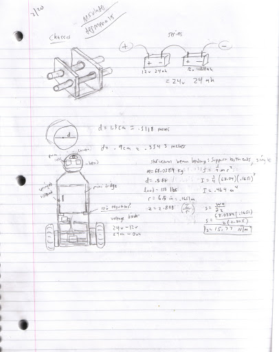
The final designs with some calculations for finding the inertia of the entire robot. Really to figure out the stress placed on the wood.
(I went with 3/4" plywood) Eventually I will paint it white.
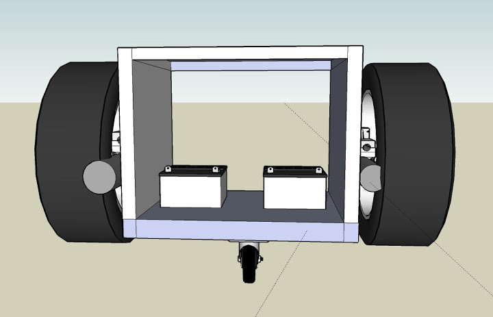
Plan rendered in Google Sketchup, obviously not drawn to scale
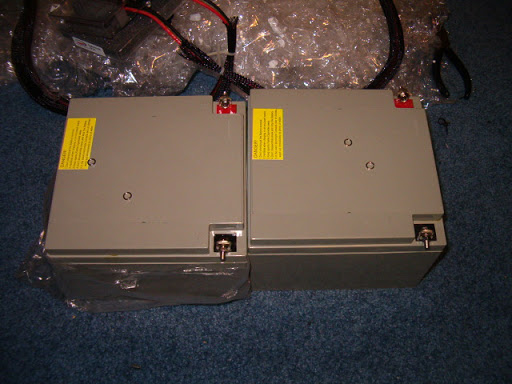
The two 12v 24AH batteries
Closer look
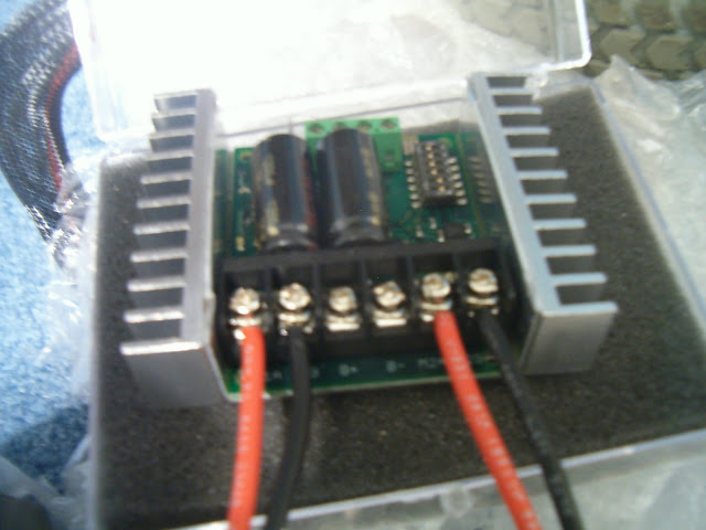
Sabertooth 2x25 Motor driver, very strong and reccommended by me! Capable of 25A load per channel, and 50A fully
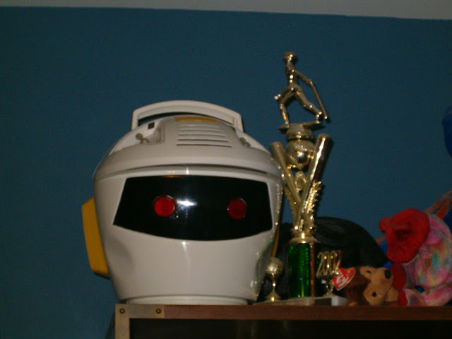
The robot head next to my 1st place baseball trophy
When I received the head from this toy:
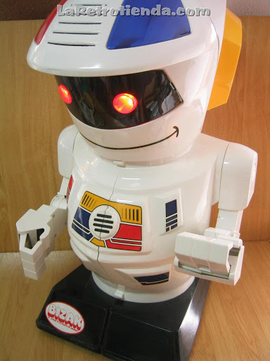
I gutted it. Of course it didnt look as nice as the model picture. I took out the leds inside as they were not bright enough, and added my own red ones for the eyes and blue leds for the headlights above (where the red and blue panels are, I took them off)
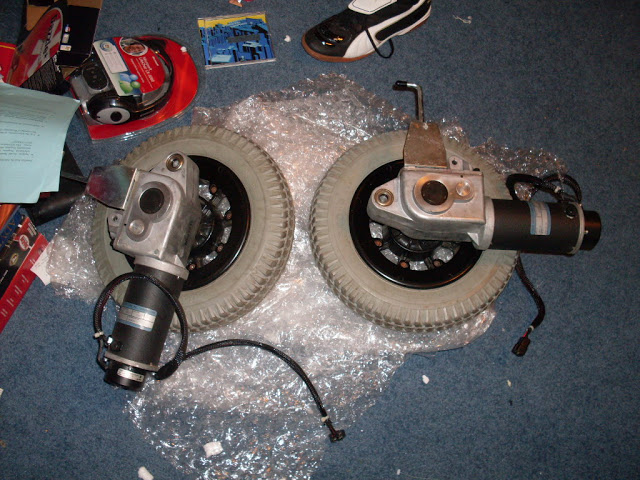
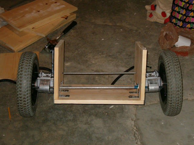
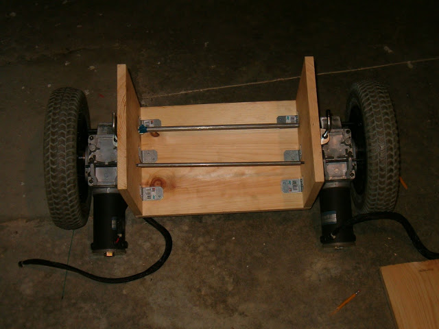
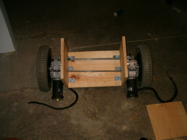
The hefty motors
~from a Jazzy 1100 Wheelchair
Edit #1:
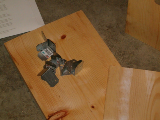
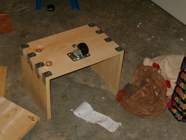
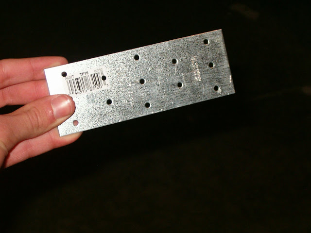
L brackets
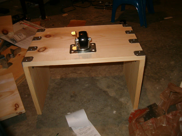
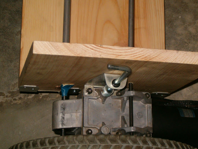
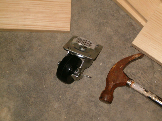
Caster not screwed in, because I need to first see if the wheelchair motors will have clearence, and everything would be flat. Yes I know thats alot of brackets, extra sturdiness! :)
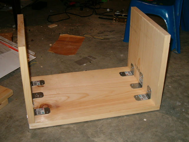
Vertical slab thingy, I needed four of these guys
I do not thinki it is going to hold at all
Future alterations:
- Use XBee Modules... to make it go wireless
- Upgrade Batteries to 72AH
Follows things with certain colors, shapes, etc.
- Actuators / output devices: 2 24v Wheelchair Motors, 1 12v springed DC solenoid
- Control method: Autonomous or Xbox 360 Controller
- CPU: Laptop
- Operating system: Windows 2000/XP/Vista
- Power source: 2 12v 24AH SLA Batteries in series, and 1 10v Ni-Ca
- Programming language: C#
- Sensors / input devices: 1.2 GHz Wireless Camera (illegal I think)
- Target environment: Indoor or outdoor
This is a companion discussion topic for the original entry at https://community.robotshop.com/robots/show/my-big-base-robot


