Ok this is a project I have wanted to do for a while now and have finally started since I needed a good topic for my Senior Exit Project.
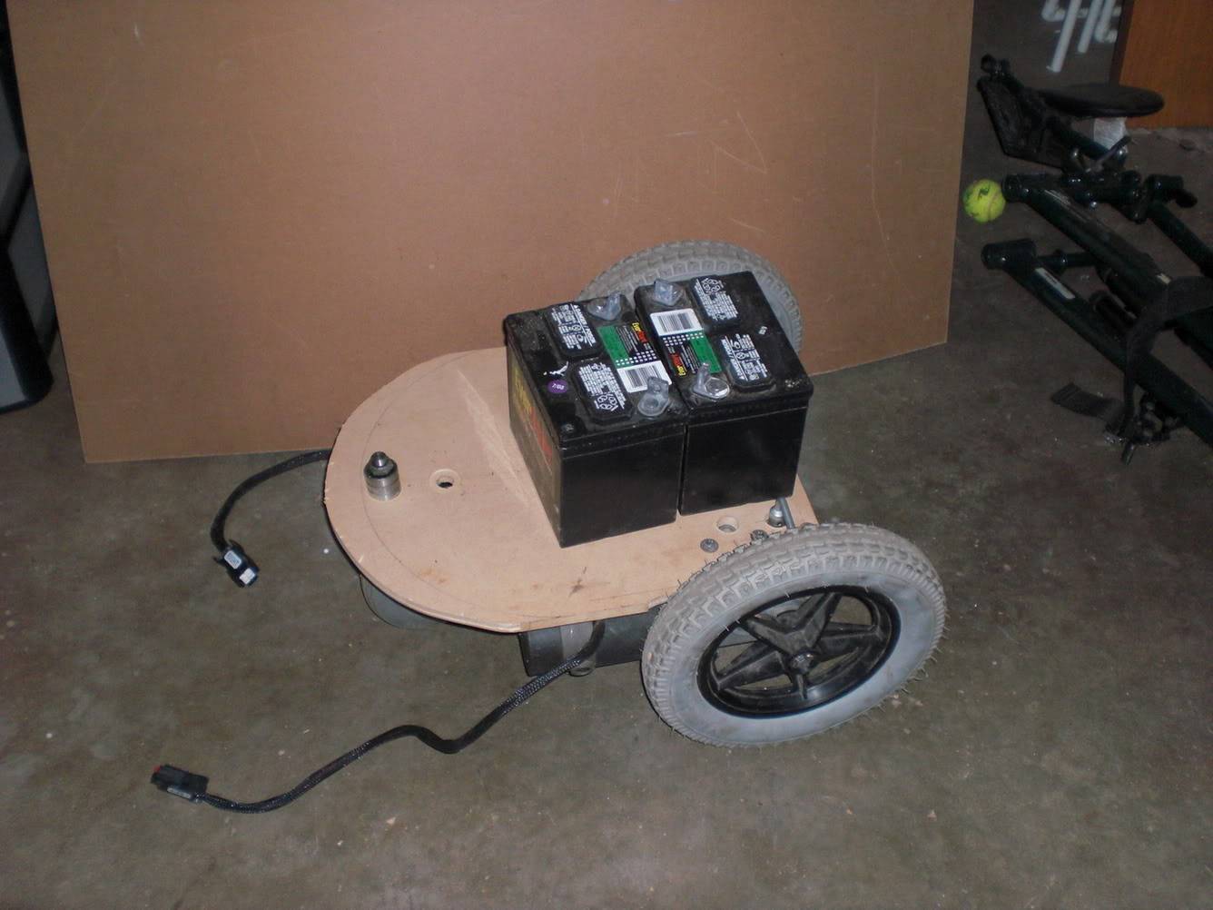
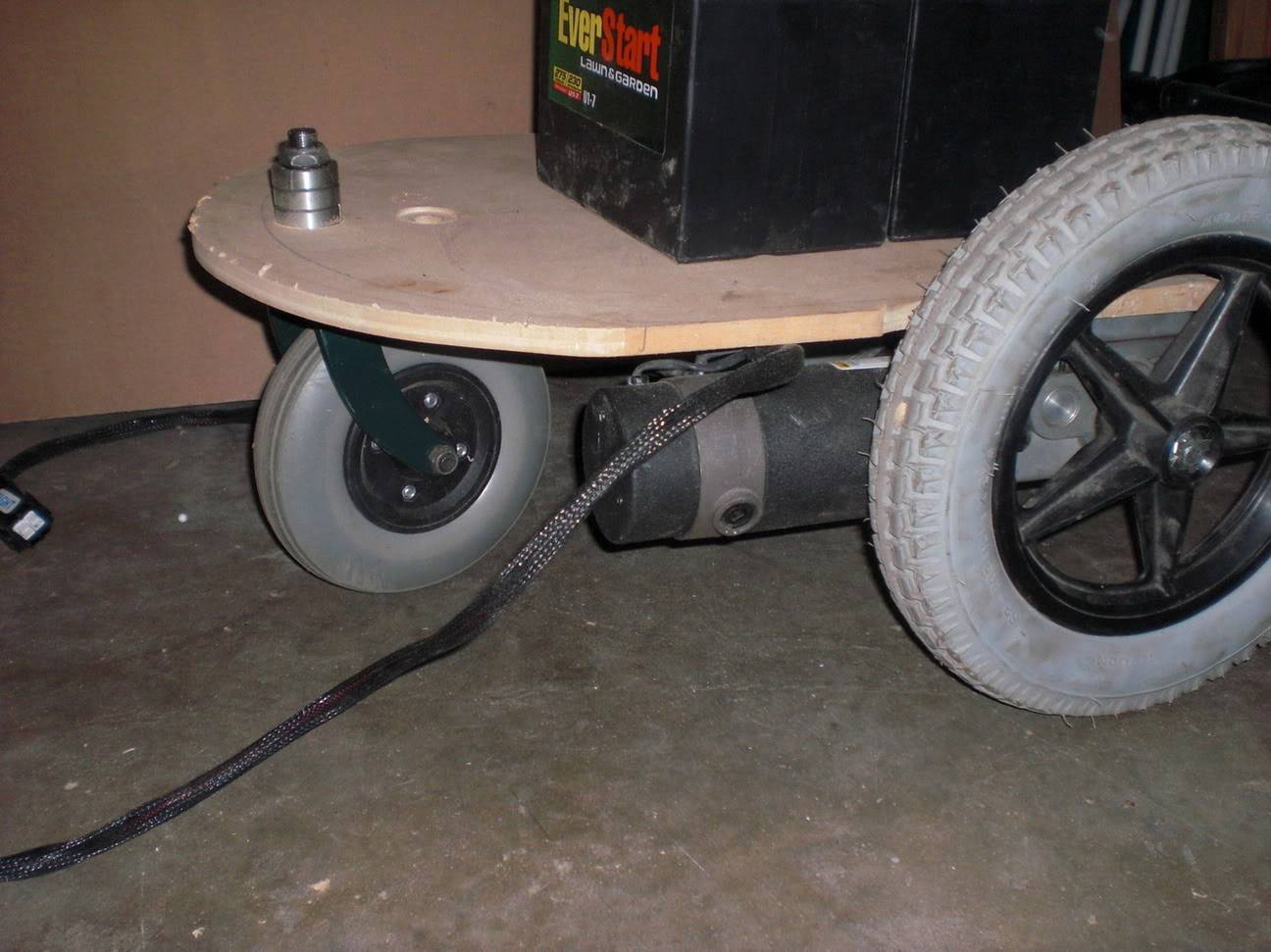
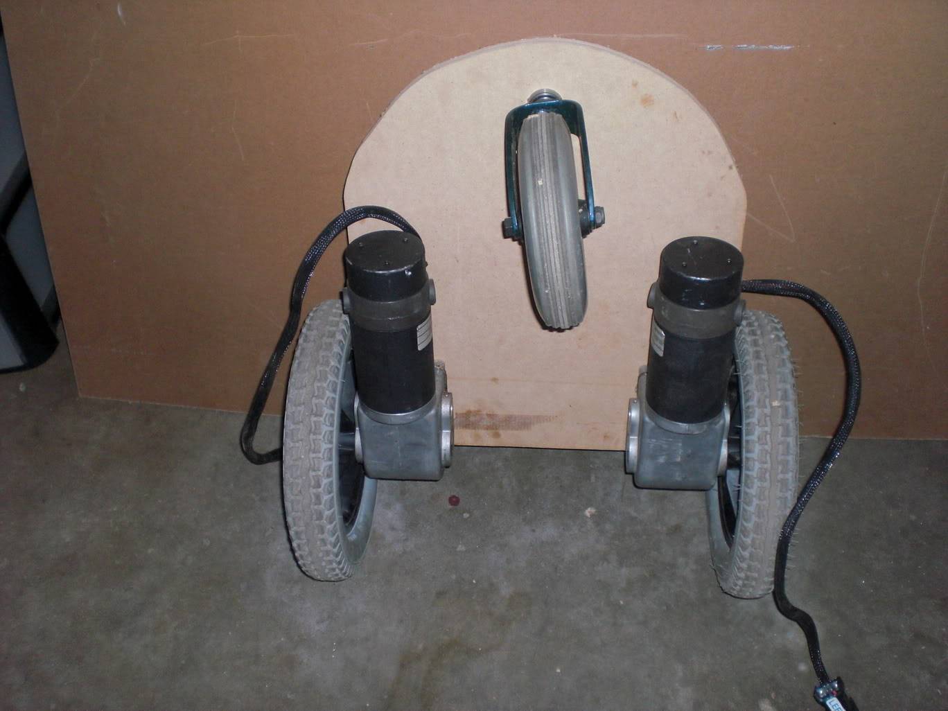
So far I have attached the two wheel chair motors that I stole (only paid $25 for the entire chair) to a sturdy platform, and added a caster in front. Doesn’t sound like much but, it is what it is for the time bean. My intent is to basically build an oversized Boe-Bot (Parallax) you know just a nice maneuverable platform that I can add sensors to and just play around with different things.
Stuff that I want to do with it but just need to find time for/ read up on:
1.IR – To since obstacles and stuff, also I love Chris’s IR Beacon idea (have the stuff)
2.Sonar – General obstacle detection and distance measuring (would need to purchase)
3.GPS – Would be awesome to have this thing drive around campus next year all on its own (have the GPS chip, but its 3.5v and my BS2P is 5v logic, any ideas)
4.Encoders – On the wheels for PID control (have two just need to make an adapter)
5.Vision – Played around with MSRS a little (have webcam)
6.Wi-FI – Have an old laptop and desktop so the only thing I need is a (piece of software)
7.Power – I want to get some better batteries (two 12v 18Ah would be nice)
Like I said so far I have just mounted the motors. Right now I’m working on speed controllers; I’m trying to design them around the HIP4082IP MOSFET driver. So if you have any thoughts on that they’d be appreciated.
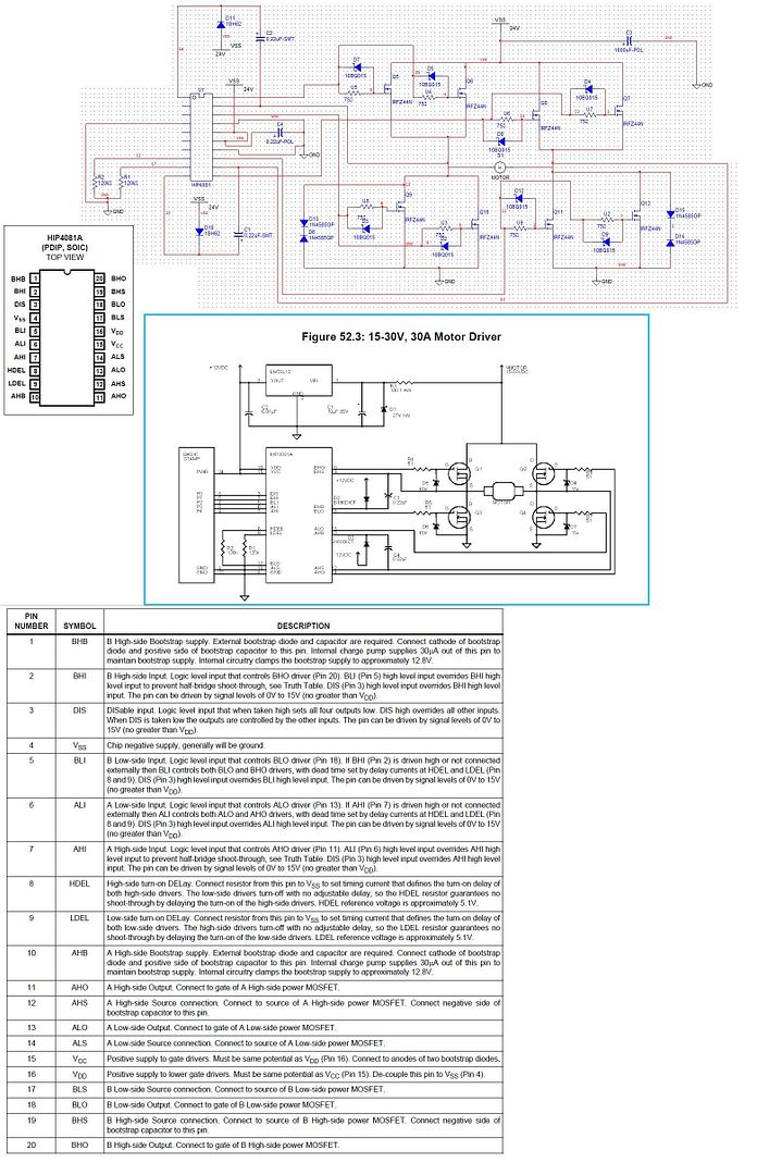
Thanks for taking a look at the data sheet, but from my understanding (though I could be wrong )the HIP 4082IP is just a FET driver. Which means it converts the 5v logic signals to voltages high enough to switch on and off the FETS. So I won’t be driving the motors directly from that chip. The motor controller that came with the wheel chair has two of these on the board next to the large FETs so I am certain that I can make them work it’s just a matter of selecting a few FETs and some diodes. Take a look at this article that I’m trying to sort of follow: http://www.parallax.com/dl/docs/cols/nv/vol2/col/nv52.pdf
Thanks,I really need to get going on this should be a fun project.
Yes I paid $25 for the entire chair which came with the sweet wheels, awesome casters, a speed controller with joystick and a few other cool parts. Thank God for thrift stores!
I sort of want to do that but it’s really not that simple. Like the control board that runs the original speed controllers is like all integrated and very complex, hosting multiple unmarked micro processors. And since my project is on designing speed controllers, it would sort of be nice to actually build one. Besides it’s something I could use multiple of, so if I can get a design that works I’ll make a few.I have a few drawings, let me see if i can clean them up and post them…
Sorry for the mistake. As you mentioned the N&V article dose make use of the HIP4081 not the HIP4082 as I said. Though I have a set of both just in case… don’t you just love free samples!!!
I don’t know if you were joking or what but I am enjoying the project quite a bit. We have to do all sorts of things like writing a research paper, interning with someone for at least ten hours, conducting at least two professional interviews, and a whole list of other things. As you could imagine a lot of the kids think it’s really dumb and a waste of time, but I think its very rewarding and an extremely good use of our time. Its worth our entire fourth quarter grade in English class so you don’t graduate if you don’t do it. Though I don’t think I’ll be done by May sixth, that is when I present what I do have along with my research, to a panel of judges so whish me luck.
Oh and what about the batteries? I know there big and heavy but they were cheap so…
Not really a mistake, both Not really a mistake, both can be used, but the 4081 should be able to go fully on or fully off since there is a charge pump working on the gate voltage. Bootstrap circuits generally only allow operation if 5% to 95% PWM is being used so that there is something pulsing to "bootstrap" a gate driving voltage from.
Question, when you solder two MOSFETs of equal value in parallel you lower the RDS (on) and more power can be dissipated right? Dose this also increase the overall ID? Like say I had two MOSFETs rated at 50A, could I control a motor that draws close to 100A? I don’t know, I’m just having a hard time picking MOSFETs and I really need to get them ordered soon! This list is intimidating: http://futurlec.com/TransMosIRF.shtml
I’m thinking about the IRL3803 but the dada sheet makes it sound like it can only handle the high current at 10v even though it can handle 30v overall. http://futurlec.com/Transistors/IRL3803.shtml
It’s always a trade off when it comes to the all the different values isn’t it.
Technically, you are doubling the current capability by soldering another FET in parallel. Practically, the case limit of a TO220 case comes into play long before the current limit does. A TO220 packaged only can dissipate 75 watts or less typcially, before a thermal failure of the internal joints occurs. Watts being I^2R losses that come directly from Rds-on. Remember to adjust the gate drive resistors if beginning to parallel FETs.
I think you can use a number of different FETs, since I seem to recall wheelchair controllers being rated at 80 watts or so. It might be advisable to look at other suppliers though, since I’ve heard a few folks mentioning long delviery times from Futurlec.The IRL3803 would probably be workable with a 12 volt supply, inductive spikes from a motor might take it over that 30volt Vds-br if used with a 24 volt supply. THe IRFZ44 oddbot mentioned is a good standard duty FET, with a 55 volt Vdss for a higher voltage supply.
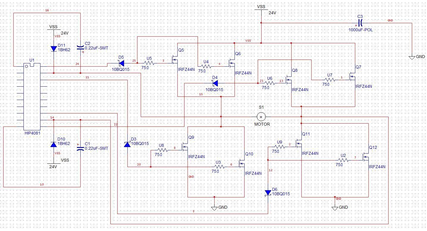
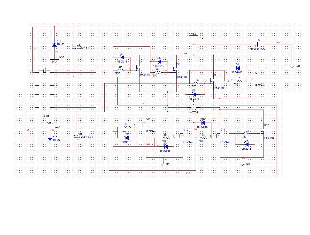
Ok for like the past three hours I have been compiling all the information I have gathered thus far, from reading your responses, the N&V article and some stuff out of my book “Intermediate Robot Building.” I have posted a link to a quick schematic I drew up. At times I don’t understand why some of these diodes and stuff have to be there but I just know they do… I read about pulling the gates low till there activated, so I mint to put 100kohm resisters going from each gate to ground but I forgot. So maybe someone could give this a quick look over and see how I have done? Sorry for the scrambled drawing, and be ware that some of the part numbers mean nothing , I just cared about the symbols…
Now that I understand the whole paralleling thing a bit better the IRFZ44 defiantly looks like a good choice, like the price too! It’s like a bucket of water the more holes you put in it the faster it will empty!!!
“Inductive spikes?”Is that where the motor is also generating electricity? And is that why we put diodes on all the FETs?
R1 on Q9 appears as a 1.5k resistor, all gate resistors should probably be around 75 ohm if paralleling 2 FETs per leg, to limit the gate driver current, and prevent any “ringing” between the capacitive gate and driver. Additionally, zeners probably aren’t needed as the HIP4081 should maintain a good gate driver voltage. Schottky diodes in parallel with the gate resistor would help in shutting down the FETs with the driver. The FETs are driven through the resistor, and pull down off through the schottky diode (pointed toward driver).
No 100k resistors on gates to ground, let the HIP4081 do its job.
Consider a ginormous low ESR cap on the motor power rails, to help suppress motor inductive kick, guessed right from the generating phase of motor control. Possible value of 500 to 1000 uF, double supply voltage rating. Can parallel a couple for easier mounting.
Possible TVS diodes across lower FETs, may be ok without them.
Oh, just saw, need to check the connections for the lower FETs, gates connected strangely. Just remove the zeners, and should be ok.
Ok I went through and cleaned it up a bit, I added the 75ohn resisters and Schottky diodes on the legs like you mentioned. I mint to ask about adding a capacitor, I’ve used Victors before, and they have a big one in the middle, just like you said 1000uF 35V. Also I read about using them on power supplies. Tell me if I have wired this right, by power rails I’m assuming you mint simply put one across +24v and Gnd. Probably needs to be closer to the FETs though, or dose it not matter?
What is a TVS diode, and why would they only be required on the lower FETs.
Hope I am making progress I really do need to get this done soon.
Slight mistake in connecting the schottky diodes. They should be in parllel with the 75 ohm resistors, not in series with them. as is, the driver will never turn on the FETs. Keeping the same oreintation, connect the anode (triangle side) of the diode directly to the gate, as well as one side of the resistor directly to the gate of the FETs. Then connect the cathode (bar side) of the diode directly to the HIP4081, as well as the other side of the 75 ohm resistor. That has them both parallel, not in series.
Yes, big cap on +24 and Gnd. Paying attention to the caps polarity
Oh, TVS diodes are Transient Oh, TVS diodes are Transient Voltage Suppression Diodes, essentially 2 diodes facing each other, to clamp voltages to a fixed level. I believe the OSMC design estimated having these on the lower legs would protect both the upper and lower FETs from flyback if needed.
Ok yeah that’s what I saw when I looked it up earlier, like a double ended diode thing. But I don’t get how it “clamps voltages” and how this is beneficial? I assume just keeping voltage out of places where it shouldn’t be. Sorry I just like to understand why these things work… Also OSMC??? Something in the data sheet maybe?
Also there are two .22uF caps and diodes closer to the chip; they were in the N&V column so I figure I need them. I don’t know if they’re going the right way or what but I think there for some “bootstrap” supply thing inside the chip. What exactly does the bootstrap do again? You touched on it in another comment but I didn’t really understand.
A TVS clamping voltages helps prevent the inductive flyback from going beyond the FETs rated Vds. The IRFZ44 are 55 volt I think, and you are running a 24 volt supply. When current direction is suddenly switched, an inductor can generate a rather large voltage trying to maintain current flow as it was originally going. This can get big enough to pop a FET, but the TVS (and big cap) can help block (absorb) the spike so no damage occurs.
The OSMC (Open Source Motor Controller) was a group effort at making a large high current h-bridge for use with Battlebots. What resulted was an h-bridge that was able to carry about 160 A continuous, probably with 400 A peaks at either a 12, or 24 volt supply. It too uses the HIP4081A driver.
I can’t say if the cap and diodes are going right either since the pins aren’t labeled/numbered on the schematic. They look kinda close, just get them to match the Nuts & Volts article and the HIP4081 datasheet and they should be fine. The cap charges up when a low cycle of PWM is going on the output, and the diode prevents the charge from flowing back when the PWM goes high, so you get the 2 together bootstraping a 12 volt supply in refernce to the source pin to drive the gate. It only lasts a little while, so another PWM cycle is needed quickly to boost the voltage back up to 12 again.
I am unsure of the connections I made for pins 15-16. The data sheet says to connect pin 15 to the anodes of two bootstrap diodes. How do I do that? And what values? I don’t understand the values of diodes so before I order parts I’ll have to figure all that out, any thoughts? For the diodes in my schematic, like the ones in parallel with the gate resistors, the TVS diodes, these “bootstraps” and the ones on AHB, BHB. Well iv posted yet another “revised” copy along with a pin out and pin description.


