Mobile Platform

The N&V article specs a

The N&V article specs a B160DICT schottky diode, 1 A (important) 60 v (overkill) high speed (important). Here they are at Digikey, check if Futurelec has something similar.

Anode, triangle side of each diode connects to pins 15 and 16 of the HIP4081A, just like in the diagram on page 3 of the datasheet and inadvertantly on page 6 of the N&V article. In the datasheet, they forgot to mark the power connections of pin 15 and 16, were in the N&V article they just connected to anodes to power, where pins 15 and 16 were already connected.

On the TVS diodes, it appears you are putting 2 strange rectifiers in place of them on each lower leg. I don’t think you understand that a TVS is a specific type, and what you have there will probably have weird results.

Also noted that you have a 24 volt supply, if that is used, a regulated 12 volts needs to be given to the bootstrap circuit and to power the HIP4081.

Ok I have made some more

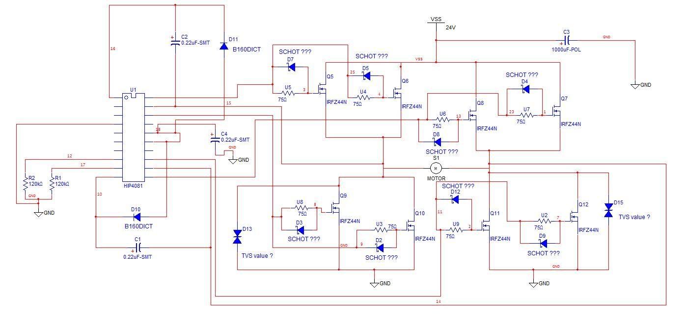
Ok I have made some more changes and think it’s about there… Though I was a bit confused by this comment “In the datasheet, they forgot to mark the power connections of pin 15 and 16, were in the N&V article they just connected to anodes to power, where pins 15 and 16 were already connected” So I hope I interpreted you right.

And no, I am not trying to put a rectifier there, I should have said something but I was just trying to make the symbol (disregarding the values), since I couldn’t find a TVS in my design software. In fact I did that a few places so I’m sorry, I know that’s really bad practice on my part. In the new drawing you will notice that I edited out the part numbers of parts I don’t know of what value to use, to eliminate any confusion.

To be perfectly honest and as you can probably tell, I’m not the most “practiced” guy out here. I mean I know a lot about circuits for someone still in high school but defiantly not enough for the things I want to be doing.

Like these diodes for example there messing me up, and I know it’s not even that hard it’s just so many values. One thing I have noticed is that voltage and wattage is used to classify them, so how to choose one I don’t know… I really need to do some more research…

Ok so this voltage regulator, anything special or just a LM78L12 like in the N&V article? I just don’t see how it can handle all the current from the battery? I mean wouldn’t it get really hot and just blow up. Anyway if so, I can build the same power supply that they have, I understand that pretty well.

Ok parts list as of now:

C1-C2 and C4 .22uF

C3 1000 uF 50V

D2, D3, D4, D5, D7, D8, D9, D12 = SCHOTTKY? N&V reads 15V but like I said I don’t know, I mean would that change since I’m using a different FET value + arrangement and at what wattage?

R1-R2 120K Ohm

U1 HIP4081

D10-D11 UF1001 (1A 50v) “Ultra-Fast Recovery”

Q5-Q12 IRFZ44

D13 & D15 TVS? Don’t know what value? Also on Futurlec there marked AC or DC, what does this mean. Probably dumb question but…

U2-U9 75 Ohm

Thanks a bunch! This means a lot to me. I’ve been told I ask too many question other places so I hope I haven’t bothered you too much. But every question I ask = more things I know.

Drawing

Checking the OSMC TVS part,

Checking the OSMC TVS part, they have a 1.5KE51CA, which looks up to be a 51v reverse standoff voltage with 1500 W capability. I don’t think the wattage is going to be that high with yours, but it’s good to have more part than you need sometimes. Closest I see on Futurlec is a 15KE47CA at 47 volts and 15KE62CA at 53 volts. I believe Futurlec is calling a bidirectional TVS devices as “AC”, and biderectional is what is spec’d on the OSMC. THe IRFZ44s are 55 volt I think, so I’d go with the lesser TVS, the 15KE47 to keep the spikes further under the FET death level.

The D2 to D12 schottky diodes should remain the same in function, since the driver is still delivering the same gate voltage and pulling it back (through the diode). OSMC has LLSD101A, which are 60v but light current Schottkys. I think the BAT42 Schottky diodes on Futurlec should work better.

Two ways of handling the 12 volt supply. Go all linear and have a step down system, 7820 to 7818 to 7815 to 7812. That way, each regulator burns off part of the heat from stepping down from 24 volts. I think since it was estimated to be a low supply of current, the N&V article just felt the 7812 reg to take all the ehat in one big drop. You could do the same, or try at least one of the added regs above. Other “more proper” way is to make/buy a switcher to efficiently drop from 24 to 12. OSMC has an LM2474HVN-12 plus the externals to get it going, inductor, cap, and UF1002 diode. The specific inductor used is a 2474-31L which is listed as a 330 uH power inductor. 0.65 ohm, 740 mA. Futurlec has a 330 uH, not sure it’s specs though, hopefully will work. The other similar switching regs available on Futurlec might have similar parts to use, just consider it as a simple circuit to get operating on its own to add to the h-bridge section later. Switchers can be a little complicated, but offer more efficiency. The 12 volt supply only needs to feed the HIP4081A, says it’s around 15 mA, but there is also the charge pump to consider too.

One other thing, you have pins 15,16 connected to ground through a cap, they are power pins, should be going to +12 volts.

Ok this is great, thanks for

Ok this is great, thanks for suggesting these parts. I feel so dumb when I add a part to a circuit, when I don’t even know why the part is there. So I’ll defiantly be researching this stuff very soon. And yeah I have pins 15-16 hooked up a little weird. I think if I do it like they did it on the OSMC I’ll be fine, which is obviously different then how I have it right now LOL

And about the power supply I think I’ll look into this switcher concept, because if it’s more effective/ proper id prefers just learn how to do it. Could I build one that works of both 12v and 24v? I’m thinking not since it outputs 12v and most the time you have to input like 1.3v more or something like that…

Sorry I don’t have more to say, I’m a little busy right now with other aspects of this project and things at school. Next time I meet with my Sr. exit mentor he will be so excited that I was able to work through this stuff and come up with a design pretty much on my own. With lots of credit in your favor of course!!! He designs circuits for a living but is currently too busy to sit down with me and start something from scratch. But likely if I can “finalize” my schematics and take them to him, he will help me create a PCB, since he has all that equipment in at his shop. Also he does a lot of embedded stuff so maybe we could add a PIC to handle all the PWM through a single wire. I don’t know just something I wouldn’t mind doing, he is getting me started on PICs so it would be good practice and it sounds fairly simple.

So looking at what I have so

So looking at what I have so far, do you think I would be fine ordering the parts we have talked about? Any extra parts I should buy in case something fails or needs a different value?