Mattingly: My first bot

Background:

Ever since I was a little kid I've wanted to build a robot.  I actually tried a few times with nothing more then some cardboard boxes and permanent markers.  (This was before I found out there was stuff IN the robot that made it do things.)

Now I've grown up and things in my life have settled to the point where I can have a hobby such as this as long as I keep the cost down wherever I can.  (And spend extravagently when I have the money and the wife isn't watching :) )  I've been waiting and saving up to build the "Start Here" bot and then the yellow drum machine (on my to do list).  But those are out of my reach financially right now.  I do however have quite a few logic chips laying around from different experiments and learnings and such.  Thus my plan is to build my first robot without the use of any micro controller.  Instead I plan to do all of the logic "long hand" and build as much of it as I can.  That really limits my options as far as my skill in electronics goes, but I think it shouldn't be too hard to make a simple bot that propels itself around and turns when it bumps into things.

The Plan:


(Update 9/23/11)

Clarification about my schematic.  The top and the bottom of each H bridge are connected to + and - respectively to power them.  I apparently forgot that part, and it's kinda important since the other legs just control it. :)

(Update 9/8/11)

Alright, so while building the final stages of the circuitry on my breadboard I realized that my AND chip was completely redundant and could be removed entirely, so I did so.  I also finished putting everything together on my breadboard and then transferred an soldered (almost) everything together.  Here is the finished schematic of my bot.

(Update a long time ago)

Using the 2 little 3 volt DC motors I bought ($7) and the electronic components laying around I'm going to build a little 4 wheeled robot that will drive in a straight line until it bumps into something; then stop, turn, and continue again.  Repeat ad noseum.  I'm not entirely sure about the final look of the thing.  I'm thinking 4 wheels, but if things work out that way it might end up with only 2 and things like that.  I will have to figure that out as I go.

Current Progress:

(Update 9/22/11)

Alright, well I put in a good days work on this last weekend and managed to get the board fully soldered together.  I then troubleshooted for most of the day to figure out why it wasn't working properly.  I managed to fix a few little problems here and there, but still can't seem to get one of my 555 timers to work.  They are both soldered exactly the same but one works properly and one doesn't so the problem must be in the solder joints I guess.  Which means I'm gonna desolder and then resolder that one this weekend.  I also figured out that I think I'm going to use wood for my wheels.  (It's free and I think I can make it work pretty interestingly if I can keep the weight down).

Hopefully soon I'll have some more pictures (and when things start getting interesting some video).  I think I need to buy a new SD card for my old crappy camera first though.

(Update 9/8/11) 

Work and a weird stomach virus have been kicking my ass so I haven't had a lot of time to work on this.  But I have managed to finish the design phase and start putting the circuit board together.  I've only got a few more solder connections together.  I also learned that from now on I'm DEFINITELY getting the boards that have the copper pads on them.

(Update a long time ago)

So far I have completed laying out the logic for the bot and how it will work.  And have completely layed out one of the motors on my breadboard which works properly.  (It goes forward until the button is hit then it reverses for a couple seconds and goes forward again.)  As you can tell from the pic, it isn't very entertaining to look at.  (Unless you like really old breadboards)  But hopefully I'll be working on a chassis and such soon, unfortunately work has been stealing a lot of my time.

I finished the other H-Bridge and set up most of the logic tonight as well as bought the perfboard and IC sockets and whatnot from Radioshack today.  (I really wish that there was another place in town that sold that stuff, Radioshack always pisses me off.)

As promised here is the logic diagram.  I couldn't find any other way to put it on here then to make it in Paint.  This consists of 2 555 timers in Monostable mode (to control how long it reverses) which feed a nand and an and chip which switches it into reverse and turns off the other motor.

Left to do: (Updated 9/22/11)

  • Set up H-Bridge for other motor DONE
  • Hook up the logic gates for other motor MOSTLY DONE
  • Set up the other switch DONE
  • Arrange and solder all parts to perfboard  DONE
  • Finish troubleshooting my first soldered board together
  • Build chassis and axels
  • Figure out material for wheels Hope that idea for wheels works

This is a companion discussion topic for the original entry at https://community.robotshop.com/robots/show/mattingly-my-first-bot

You will need gears or

You will need gears or something to increase the torque and reduce the speed of your little 3V DC motors (unless they already have a gearbox attached). You might be able to salvage some pulley wheels and drive bands from old VCRs or elsewhere for this purpose.

There are some pretty simple circuits that use a relay, a LM386 op amp and some other simple components to do the ‘hit something, backup and turn’ technique. Look for ‘Mousey the Junkbot’ for ideas.

Good luck!

** that reverser would be the**


that reverser would be the 74AC14 or 74HC14 hex inverter IC.
a versatile and easy to use chip,

the original herbie:

|x

with reverser:

Herbie with reverse.png

some other things u can make with it include:
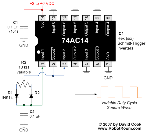
a PWM controller where the frequency is set by a capacitor, and the duty cycle by a trimpot.
u can make 3 of these on 1 chip.


VariableDutyCycleSchematic.gif

http://www.robotroom.com/PWM.html

also check out this large collection of BEAM circuits:
http://costaricabeam.solarbotics.net/Circuits/Vores_Main.htm
also if you are not familiar with BEAM robotics, you should definitely do some googling on that,
as it is an entire class of robotics based on using those logic chips, particularly the 74 series.


Wow, thanks for all the info

Wow, thanks for all the info guys.  After I do some more work on my circuits tonight (gonna build the other H-Bridge and do some battery testing) I’ll see about putting a schematic up or at least a simple logic diagram.  One of my first thoughts was setting something up using the 74HC14 but decided to go anohter way with it instead.  I’m using 2 555 timers, and 2 74HC chips (1 AND and 1 NAND) I had lying around from going through the Make: Electronics book.

you may also find this

you may also find this interresting:

http://www.reddit.com/r/electronics/comments/fsjno/simple_555_timer_based_servo_controllers_for/

its a bunch of info and ideas about 555 based robots revolving around a 555 servo controller.
i think with this you should be able to use servos with the same type ofstrategy and components you
are using now.
might come in handy for future projects.

incidentally, that servo stuff was a winning entry in this 555 design contest:
http://www.555contest.com/news/
truely amazing what you can do with that little guy.

Have I mentioned that you’re

Have I mentioned that you’re awesome?  Thanks!  I’ve actually been wondering about ways to control a servo (I’ve got a few mini servos I got for almost nothing) without a micro controller, but since my oscilloscope can’t sample nearly fast enough to see what my reciever’s output is to the servo.  (I think it spends most of it’s time near 0 volts but also goes up to 3 about 1/6th of the time but it’s hard telling without a much nicer oscilloscope. :slight_smile:

I’m probably going to “graduate” to a micro-controller as soon as this bot is done as a bit of a reward for completing my goal.

Regarding one of your 555

Regarding one of your 555 timers not working, are you getting any output from it at all?

From reading your post, I think you are using IC sockets, which I strongly recommend for all your ICs. This way, you solder to the socket, and insert the IC chip later. It also makes it easier to replace fried chips.

If you used a socket, I imagine your problem is not that you overheated and killed your chip.

If you are concerned about your soldering, check out one of the many fine videos on YouTube on how to solder. Five to ten minutes of your time invested, and you’ll learn skills that are simple and will stay with you for your whole life.

Have you looked at the PIcaxe line of micros?

If money is tight then the picaxe is your best choice for cheap microcontrollers. The are also the easiest to get started with. The chips themselves run from $3 to about $9 last time I looked. the programing circuit requires only 2 resistors. and you can make the programming cable yourself. I have a Picaxae book that I have been wrinting that is available from my website (free just download it) that will help you get started with the picaxe. Please ask questions and don’t feel as if you are bothering us we do not mind helping you learn beacuse that is how many of us learned. The Web link is below.I mostly do animatronics but I am now building robots. They are very similar with many of the same circuits. I am still working on the book but there is enough there to get you started.


http://www.freewebs.com/hpropman/


Wow, people are actually

Wow, people are actually reading this?  I have to say I’m honestly a little more then surprised.  I thought I might get some people to watch a video, but not read my boring updates. Thanks everyone for checking in on this!

I looked up a bunch of youtube videos on how to solder and am definitely using IC sockets, I even swapped out the 555 for another and it was still not outputting anything at all.  My voltmeter is telling me that my trigger is working properly so it’s really weird that I"m not getting any output from it.  I was thinking today at work that there is a chance that I accidently put my reset to the wrong one.  (I don’t remember off the top of my head, but I think + will reset the chip)  So, if I did that I might just be constantly resetting it not giving it a chance to kick out a voltage.  I hope that’s it, easy fix. :slight_smile:

As for my soldering, I’m just inexperienced.  Before this board I’d only ever soldered a couple of things together before, and looking at my joints you can tell where I started and where I ended because I got a lot better in the process. :slight_smile:  I should have probably started with something easier then this as my first one, but I have a tendency to just dive into things.  For example, I bought the soldering iron and soldered for the first time on my laptop to replace a busted charging plug. :stuck_out_tongue:

Thanks for the

Thanks for the reccomendation.  I was looking at Picaxe stuff and will probably be buying those first.  I think I want to start with a decent project board first though for something nice to play around with and learn.  Also the cable thing is one of the ones slowing me down the most, I don’t think my computer has the right serial plug to use the cheap cable and the USB ones are a crapton more expensive then they seem like they should be.  If I can make one that’ll definitely make this something I can do a lot sooner.  Also before I buy one I’m gonna do a bunch of research and check through the forums to see what people like/suggest.  (I might start a topic if I can’t find any info.  I tend to troll if nothing else because most of my questions are already answered somewhere on there and I hate re-asking things. :slight_smile:

Also thanks for the link I’m gonna bookmark it and read through when I get a chance, very awesome of you to put that info out there for people.

No such thing as the “wrong” serial

If your PC has a 9-pin male D-sub connector on it, that’s a serial port - no other peripheral on a computer uses that port.  VGA monitor cables are similar, but the connector on the PC is female, as opposed to male, and they’re 15-pin.

As long as it’s enabled in your computer’s BIOS you’re good to go :).

Oh, I thought that the mouse

Oh, I thought that the mouse and printer ports were serial as well as the old school (pre usb) big printer ports from the late 80’s.  Either way I don’t think this little crappy computer has one of those. :frowning:

check your mainboard manual,

check your mainboard manual, there may well be a serial pin header on the board somewhere.

The large female DB25 is a

The large female DB25 is a parallel port and the male DB9 is serial.  Mice used to use serial, many many years ago, but the PC abandoned serial mice long ago in favour of PS/2 ports (the round ones), which was then superceded by USB.  

I might not know that much about microcontrollers or electronics, but I do know rather too much about PCs!

You should be able to get USB to serial converters really cheap these days - under £5, even: http://www.kenable.co.uk/product_info.php?products_id=1616