


Mattingly: My first bot.
Background:
Ever since I was a little kid I've wanted to build a robot. I actually tried a few times with nothing more then some cardboard boxes and permanent markers. (This was before I found out there was stuff IN the robot that made it do things.)
Now I've grown up and things in my life have settled to the point where I can have a hobby such as this as long as I keep the cost down wherever I can. (And spend extravagently when I have the money and the wife isn't watching :) ) I've been waiting and saving up to build the "Start Here" bot and then the yellow drum machine (on my to do list). But those are out of my reach financially right now. I do however have quite a few logic chips laying around from different experiments and learnings and such. Thus my plan is to build my first robot without the use of any micro controller. Instead I plan to do all of the logic "long hand" and build as much of it as I can. That really limits my options as far as my skill in electronics goes, but I think it shouldn't be too hard to make a simple bot that propels itself around and turns when it bumps into things.
The Plan:
(Update 9/23/11)
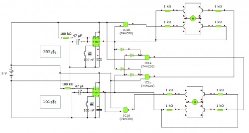
Clarification about my schematic. The top and the bottom of each H bridge are connected to + and - respectively to power them. I apparently forgot that part, and it's kinda important since the other legs just control it. :)
(Update 9/8/11)
Alright, so while building the final stages of the circuitry on my breadboard I realized that my AND chip was completely redundant and could be removed entirely, so I did so. I also finished putting everything together on my breadboard and then transferred an soldered (almost) everything together. Here is the finished schematic of my bot.
(Update a long time ago)
Using the 2 little 3 volt DC motors I bought ($7) and the electronic components laying around I'm going to build a little 4 wheeled robot that will drive in a straight line until it bumps into something; then stop, turn, and continue again. Repeat ad noseum. I'm not entirely sure about the final look of the thing. I'm thinking 4 wheels, but if things work out that way it might end up with only 2 and things like that. I will have to figure that out as I go.
Current Progress:
(Update 9/22/11)
Alright, well I put in a good days work on this last weekend and managed to get the board fully soldered together. I then troubleshooted for most of the day to figure out why it wasn't working properly. I managed to fix a few little problems here and there, but still can't seem to get one of my 555 timers to work. They are both soldered exactly the same but one works properly and one doesn't so the problem must be in the solder joints I guess. Which means I'm gonna desolder and then resolder that one this weekend. I also figured out that I think I'm going to use wood for my wheels. (It's free and I think I can make it work pretty interestingly if I can keep the weight down).
Hopefully soon I'll have some more pictures (and when things start getting interesting some video). I think I need to buy a new SD card for my old crappy camera first though.
(Update 9/8/11)
Work and a weird stomach virus have been kicking my ass so I haven't had a lot of time to work on this. But I have managed to finish the design phase and start putting the circuit board together. I've only got a few more solder connections together. I also learned that from now on I'm DEFINITELY getting the boards that have the copper pads on them.
(Update a long time ago)
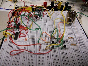
So far I have completed laying out the logic for the bot and how it will work. And have completely layed out one of the motors on my breadboard which works properly. (It goes forward until the button is hit then it reverses for a couple seconds and goes forward again.) As you can tell from the pic, it isn't very entertaining to look at. (Unless you like really old breadboards) But hopefully I'll be working on a chassis and such soon, unfortunately work has been stealing a lot of my time.
I finished the other H-Bridge and set up most of the logic tonight as well as bought the perfboard and IC sockets and whatnot from Radioshack today. (I really wish that there was another place in town that sold that stuff, Radioshack always pisses me off.)
As promised here is the logic diagram. I couldn't find any other way to put it on here then to make it in Paint. This consists of 2 555 timers in Monostable mode (to control how long it reverses) which feed a nand and an and chip which switches it into reverse and turns off the other motor.
Left to do: (Updated 9/22/11)
- Set up H-Bridge for other motor DONE
- Hook up the logic gates for other motor MOSTLY DONE
- Set up the other switch DONE
- Arrange and solder all parts to perfboard DONE
- Finish troubleshooting my first soldered board together
- Build chassis and axels
- Figure out material for wheels Hope that idea for wheels works