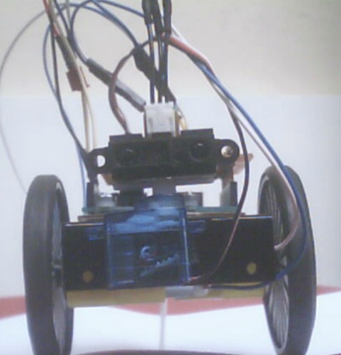
So after putting together and taking apart a few prototypes starting with this ugly mofo I'm finally arriving at something I like. It's a simple start here class sorta robot allthough it has a specific purpose which is: environment mapping. Therefore it is outfitted with a pair of homemade wheel encoders, so that I can measure how much the wheels are turning, and thus calculate how far it is moving. I'm having a hell of a time getting the encoders to work properly though. These IR sensors are very sensitive and the slightest change in light, distance or angle messes up my readings :(
Anyway for now I'm calling it Mappy. I'm also considering simply MapBot. Or perhaps RoboBob. My girfriend thinks it's extremely cute and wants me to name it after my petname for her which is Miti. Perhaps Miti2.0 has a bit of a ring to it :D
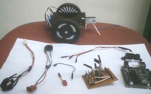
In the process of creating this bot I had to make a shield for my Arduino, which has now been expanded to connect the two QRB1134 sensors for the wheel encoder. Here are the parts of my robot separetely:
Future plans for Mappy..well 1st of I wanna get the encoders to work smoothly, and then start doing some PROGRAMMING!! Wheeepeeee!! But I'm also planning to add two frontal bumper sensors and at some point I wanna add an extra servo to make a pan and tilt mechanism for the IR sensor AND I wanna add OddBot's compound eye too (I bought one when I ordered a bunch of motors and servos recently).
For now it's powered by an AT power supply and sends the mapping data to my PC via USB, but I'm planning to get 4 x NiMH AA batteries and a bluetooth module ASAP to make it truly mobile.
.....:... Aniss
Environment mapping (soon I hope)
Actuators / output devices: 2 x DC motors and 1 x microservo (from DAGU)
CPU: Arduino Duemilanove (328)
Power source: AT power supply (later 4 x NiMH AA batteries)
Programming language: C++, Arduino
Sensors / input devices: 1 x Sharp GP2D12, 2 x QRB1134 (wheel encoders)
I have played with those sensors for wheel encoders and wasn’t happy about how they work. That is why I went for motors with built in encoders. I chose the Faulhaber motors because they were cheap and silent (I hate noisy motors). I still have problems with Arduino counting properly in half quadrature mode (change interrupt on Ch A and check Ch B to determine the direction). For your sensors (and perhaps for mine too) you will need a trigger Schmidt IC so it will automatically debounce them. Or, you can buy the Hammamatsu IR sensors that have the trigger incorporated.
I kinda like it too. It’s tiny, compact and no unnecessary bits anywhere. Another reason to name it after my girlfriend. She is 1.52m and weighs like 40kg.
But it’s a bummer with the encoder. I tested it quite a bit and got some OK results. But now it’s not working at all. Dunno why? Either it’s counting too fast or too slow.
I just realized that I forgot to put a cap between the signal and the ground of the IR sensor. I’ll try adding it ASAP. I actually used a 0.1uF ceramic cap on my test setup and it’s also on the schematic I used to hook it up:
I'll also try printing out the encoder discs with a better printer and test it a bit more. But it's not easy to make sure that the distance between the disc and the sensor remains exactly the same when the wheel is turning. I think that may be one of the issues.
Otherwise I guess I'll have to get one of those Schmidt-thingies you mentioned allthough I have no idea what it does or what to do with it. But I just read here that it is recommendable. LMR member Big Face has seemingly had succes with his encoder setup using a similar IC.
Thanks for the input :)
PS: Another option would be to buy a couple of rotary encoders if I can find some with a proper resolution that aren't too pricey.
I have tried to use rotary encoders - the scroll wheel from a mouse, but hey are mechanical and as any mechanical switch they bounce and desperately need debouncing. They are made for very slow speeds, as wheel encoders, they will lose counts. So the only way out will be: use a laser printer to print the pattern so you have sharp edges and use a Schmidt trigger IC. Better yet, use a dedicated encoder counter, that one has everything integrated.
For now, I am going to use just one channel counts for both edges and keep track of direction in software. I might use a pin change interrupt for the second channel that will quadruple the encoder counts from 141 to 564 clicks/rotation. I have added PinChange interrupt to my Arduino interrupts library, if you need it, I’ll post it for you.
However I’m not sure that rotary encoders are necessarily machanical. I have seen some that seem to be optical and some of them we even quite cheap. Even cheaper than this Hammamatsu sensor you mentioned.
A few seemingly optical encoders I’ve been looking at:
Since you are using servos, here is a thought I had a couple years back (I also wrote this in another thread):
replace the pot in the servo with a rotary encoder (unfortunatelly the pot shaft has 5mm dia and most encoders have 6mm shaft…)
replace the electronics with a custom board that uses a tiny45(or 85) and a single H-bridge (FAN8082 for example)
use I2C for communication
I looked at the encoders you listed, the one before last has a variant with 5mm shaft, but has only 16 clicks/rotation; the last one has 6mm shaft, but has 128 clicks/rotation. Now if this one had a 5mm shaft I would get a couple for my servos…
It seems that all of them have some bouncing and a few of them have even low RPM (lower than the about 60RPM a regular servo has). This means my motors probably have that too. I should look at the signal on a scope then decide if I’ll do something about it or not. Right now I have other fish to fry…
About the code, I think you mean the modded interrupts library, right? I’ll attach it to my robot’s page, you can also look at the encoder code over there. As for the Schmidt trigger IC, I have no idea what to recommend as I haven’t used any. But I’ve seen it mentioned a few times browsing robot pages over the net, can’t remember where at the moment…
I’m using 2 DC motors and an L293D H-bridge, so basically you’re suggesting to start all over
I think I’ll try some other solutions 1st. For starters I’ll reprint the discs, add the cap and check out this Schmitt-thingy. Otherwise I might buy an encoder and figure out how to attach it to the shaft of my DC motors. Or perhaps buy some motors like yours…only you’re also having problems so I dunno?!
I may also try to see if I somehow can code my way out of it. Currently I’m using the digital input with the QRB1134 sensor. However I took a look at the analog signal using my homemade software oscilloscope.
Here is what it looked like when with a white object in front of it:
And when nothing (or a black object) is in front of it:
I'm thinking..If I average out the values and use a smoothing filter like this one (which BTW I built into my scope too) I may be able to detect a change that way. Even if the difference between black and white is only (averagely) 0.1V or something that may be enough? I dunno?! But it's worth a shot..
That never occured to me. I’ve seen several examples on how to hook up these things and the other resistor seems to vary a bit (between 100 and 330 Ohm), but the pullup ALWAYS seems to be 10K.
Anyway I have a few 10K resistors left so I’ll try to connect 2 and 3 of them in parallel. That should give 5K and ~3.333K respectively. Hope it wont fry anything
If you don’t use servos, don’t worry, you didn’t lose anything. And you don’t need to start over. For some reason I thought you are doing something similar with what Rudolph is doing, only outside of the servo.
Pull up resistors will make the voltage level for HIGH to get lower or closer to the 5V and the sensor might get more or less sensitive to switching between white and dark. You also need to play with the distance to the pattern and with the amount of IR light the sensor shines on the surface (the other resistor).
From your oscope readings I get that there are lots of interference that can be created by a too high pull up resistor, a pattern wheel somewhat too shiny for IR light, reflections of too much IR light from surrounding objects (wheel spokes…).
I read somewhere about the pattern wheel, it seems the best way to do it is on photo paper on a laser printer with the settings maxed to the dark (highest density, darkest print). A shiny photo paper will need just a tiny bit of IR light shining from the LED, that way there are no reflections from elsewhere.
Anybody who gets those things to work for them deserves kudos. I’ve tried working with them, and it always seems like electronic voodoo to me, not the good kind either.
And as I recall you were planning to make encoders based on hall effect sensors and magnets…How did that turn out? Judging by your comment not as well as you had hoped for
Have you tried to replace Have you tried to replace your resistors with pots to see if you can dial in the correct resistance values to set both a zero for white and a value large enough for black so it picks up the encoders correctly?
So far I’ve just been trying out different resistor values. Respectively 110, 220 Ohm for the LED resistor and 10, 5 and 3.33 K for the pullup. However the readings didn’t seem to improve at al.
But you’re right I should go buy some pots and try it. I just don’t have any and actually I never used one before (embarrasing). And even if I manage to dial in the right values I’m not even sure how I can know what the exact values are (even more embarrasing).
Tweak the pot until you get Tweak the pot until you get the right sensitivity, then take out the pot and measure the resistance it’s set to with a multimeter.
Unfortunately I still don’t have one. And my robot budget is running low and my parts/tools wishlist is looooong and growing.
Anyway I’ve sorta been using my Arduino analog inputs as a multimeter so far. That is when I wanna measure voltage (up to 5V) and current (using a shunt resistor). Is there a way to measure resistance that way?


 She is 1.52m and weighs like 40kg.


