

UPDATE: Nov. 30th, 2012: Progress report with pics, no new vids.
Introduction: Well, I meant for this to be a draft but you need to make sure the box is checked or it isn't happening LOL The reveal of yet another unfinished project is done. Might as well flesh it out.
This bot is a tribute to lumi's EL2ISA2 R2 candy tin bot. He made such a cool, well-travelled pocket R2 that I had to have my own! What really made it for me was the mini sound module he found that let the bot make those critical beeps and boops.
So I set out on making a clone but with an ATtiny85 driving a simple PWM audio playback circuit. I found I wanted more control over the audio playback though. Then I found the SOMO-14D type module with it's sleek miniature size and realized I needed more I/O pins to control it.
That begot the quest to control an L293D chip with just one pin instead of the usual four. After I sorted that out then it was onto edge detection to give it another level of deskbot-savvy. Several incarnations later I came up with the setup you can see somewhat in the drawings in the whiteboard pic.
Right when I felt satisfied with the plan I found super-super small 2.5g 1.9g servos and I had to work on making the head move. Soon after that I had an idea to make a 555 circuit to give some randomness to LU2's red/blue headlight.
Then I remembered a charging plug might be nice since the battery is buried. And a programming jack would be almost essential as the PICAXE will be soldered directly onto the board. Wait, I forgot to add a power switch! Hmm... There's no way to make this circuit fit if it's a through-hole design. I guess I'll try my hand at some SMD hand soldering too, why not.
So what began as a simple copycat project turned into a quest for the smallest-yet-affordable components to make it all fit. These are some pics I shot earlier today testing my new Samsung S3 phonecam...
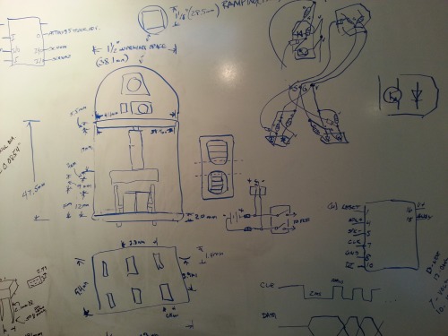
The white board, where it all starts.
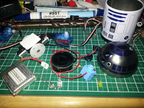
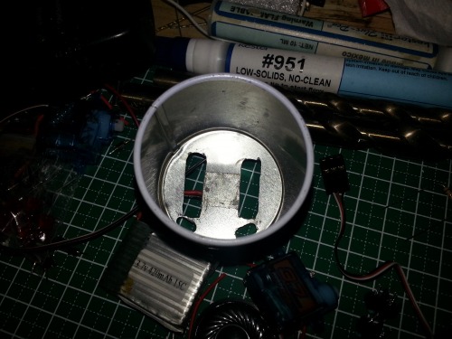
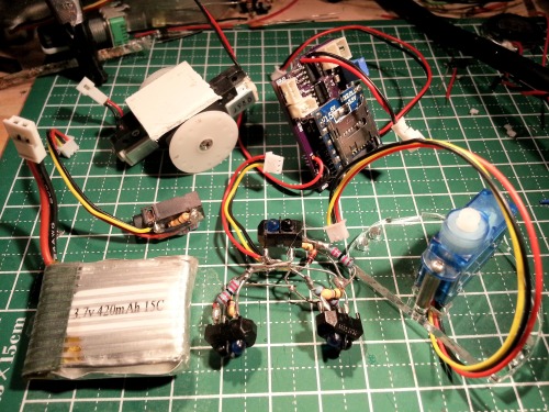
A pic of most of the non-circuit board mounted components. I couldn't get the mini servos to work but the enormous (in comparison) 3.7g servos from HobbyKing will work after all.
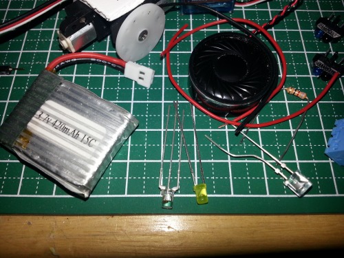
The perfect fitting lipo, a blue-red fun LED, a serious undervoltage yellow LED, and the luminosity sensor. Black wad is an 8ohm speaker.
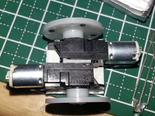
Using the same motors lumi used in his EL2ISA2 bot.
Slots for the wheels. The holes in front of them are for edge detection.
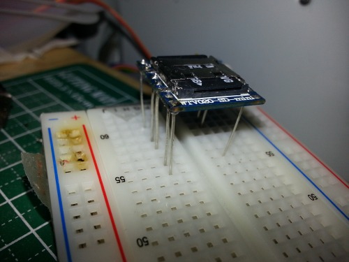
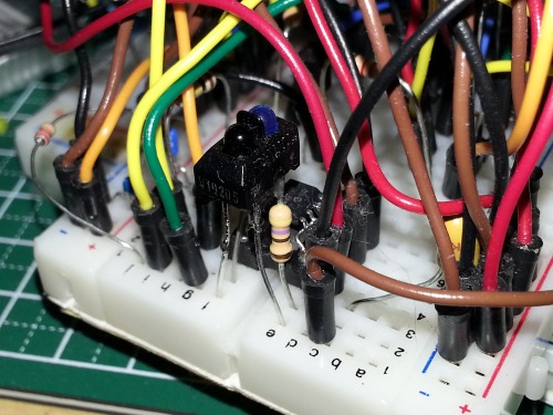
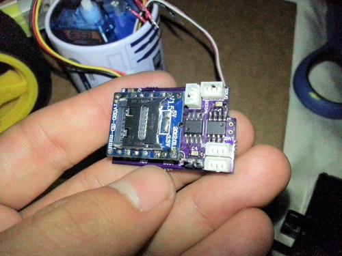
The audio module with its machine pin headers removed and some scrap leads soldered in for breadboarding.
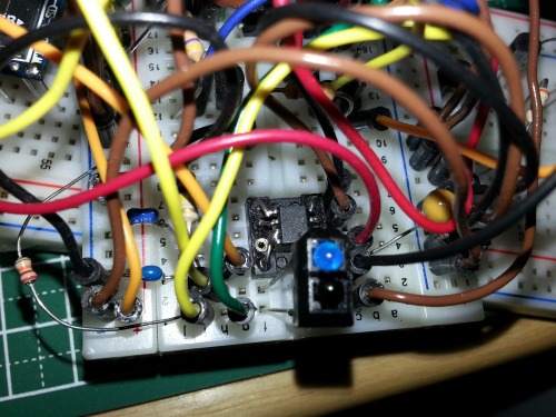
The breadboard with the main circuit rides sidesaddle next to the audio module.
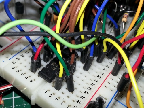
PICAXE 08M2 rows 16-19, L293D rows 22-29.
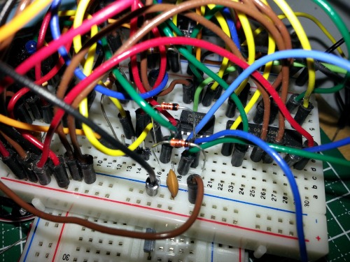
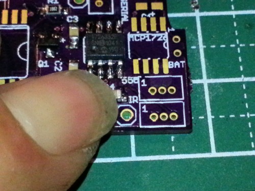
All the IR sensors are hooked up to one input. The signals are isolated by SD103 diodes. These are two of the three to be used. You can see the three-pin servo header poking out too.
One of the test IR sensor setups. The 3.3V voltage regulator is behind it.
Closer view of the regulator. I have some more scrap leads that are soldered to the chip and then soldered into the holes of a DIP8 socket.
UPDATE: Aug. 1, 2012:
I got to building the IR sensor array this evening. I decided to flex my skills honed from BEAM bot building and freeformed the whole thing. It took a little longer than I expected but hey, what doesn't? :)
There is one forward looking sensor and two underside sensors, one in front of each wheel for edge detection. All three are TCRT5000's running under a regulated 3.3V voltage regulator. I've got the forward sensor wired reverse of the undersides. A proximity detection for the obstacle sensor is bad whereas proximity underneath is good. I found 22K resistors allowed the swing in the sensor's analog voltage to be great enough as to act like a digital sensor. All three outputs have an SD103 diode on them and they are all wired into one input. Controlling the bot with only one input works because no matter what happens there is only one response; back up and turn.
So, here's the nest of leads and solder that resulted:
The IR sensors with the resistors and diodes soldered on. Got to have the motor unit in there to make sure it fits. Very tight.
After countless adjustments I started getting things into position for soldering.
All three sensors hardwired together and a three-wire JST ZH 1.25mm connector cable soldered in.
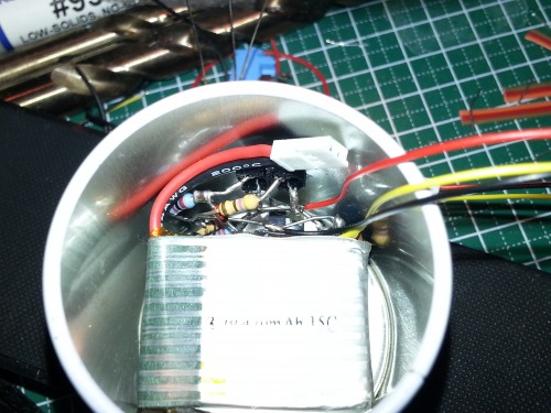
FInally got my camera settings somewhat dialed in lol. The choice in battery couldn't have been better. Look how that battery sits in there all snug like it was meant for this bot, not some tiny RC heli.
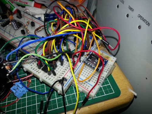
The rest of the robot's circuit is ready to test this amalgam of material. Hopefully I can get some time in the next couple of days to give it a go.
August 18th, 2012 -
Got around to coordinating the motor control with the IR sensors. Uploaded a video for kicks. Also did a little tinkering with the chassis and such.
The head fit was just too snug for the little servos so I ground down some material where the two sections meet. Nice and loose now.
I needed some supports to make a shelf to support all the components and PCB over the battery. I cut off a strip of 1/4" expanded PVC/Sintra.
Nice fit.
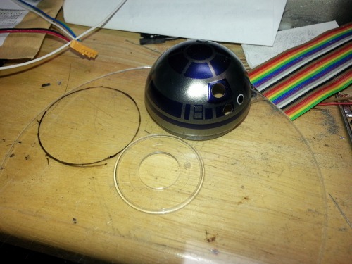
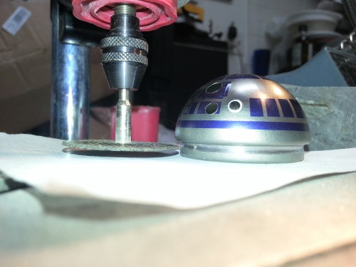
I decided that polycarbonate would offer reasonable stiffness vs. thickness. One of those filler DVDs from a spindle pack was recycled. I cut it out with a rotary tool in a drill press stand using an 1/8" multibit.
I sanded down the disk and was getting ready to drill a hole for the power switch when I glanced outside and saw the sun shining and the plants glowing. It looked like they were onto something so I went outside and joined them.
UPDATE: Aug. 27th, 2012:
I was surprised whe the replacement audio modules came early a few days ago. I cursed myself because I'd delayed sending off the PCB plans for manufacturing because I thought the module delivery would take longer. Now the project is on pause because I'm waiting for circuit boards now. I wanted them to be ready when the modules arrived. It turns out to be a blessing because despite my best efforts I couldn't get the WTV-20 module to talk its weird SPI to the PICAXE. Perhaps I've been sent two more non-serial mode modules but I doubt it for several reasons. Anyhow I've got a workaround I'm satisfied with but the original PCB design wouldn't have worked, maybe as an incense holder. Sometimes it's good to be a procrastinator.
The workaround also freed up an I/O pin so now I can stop the motors by toggling the enable lines on the L293D chip. In the video you can see the way it responds to obstacles and edges as well as some of the random stopping, head turning, and beep-booping programming. I want to have it stop more often and I think I'm going to try a different head turning algorithm. I'm not sure I'm happy with the current level of "randomness."
Next step is to redesign the main PCB with the new changes and send boards to OSH Park for fabrication. I've already started growing out a couple obscene looking fingernails in preparation for fiddling with tiny SMD components.
September 19th, 2012 -
My bag of PCBs from OSH Park arrived a couple of days ago so I finally got to test out my "Bioengineered SMD Manipulators." I don't have a hot air rework station. I don't have a hacked toster oven. But I do have a small tip for my iron and said Manipulators:
Above is a 0805 package capacitor about to be soldered in. First I melt a very small amount of solder to one of the pads.
Then I use my Bioengineered SMD Manipulators to hold the cap down over the pads. Then I touch the tip of the iron to the tinned pad/cap lead.
This tacks the component down. Then I can go and do a good solder job on the other lead. I come back to the tacked down lead and give it a proper connection. The board is approximately 1" x .75" IIRC, can't find the specs at the moment. It was not as hard as I thought to solder the 0805 package. The Manipulators definitely helped :)
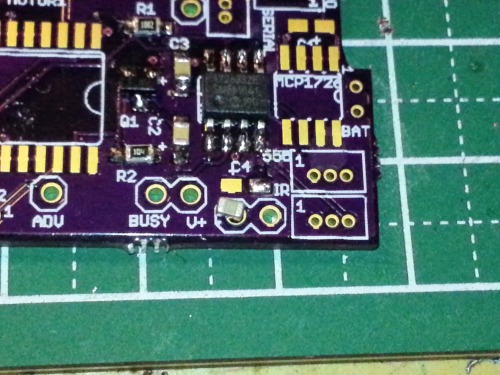
If you have the keenest eyes and the sharpest awareness you'll notice the MCP1726 voltage regulator is soldered into what should be the PICAXE 08M2 position. After digging out another board and getting to the same point in the build, I came to find I've lost all my SMD PICAXEs. The density of my workshop is so massive that if it implodes, I think it will turn into a black hole instead of a white dwarf. Who knows if those chips are even in The Pile. I've already placed an order for a trio of replacement 08M2s as opposed to looking for a needle in a stack of needles.
One of the logistical problems I ran into was mounting the mini servo to the support shelf. Although handcrafting the mouinting posts was not impossible I was more inclined to buy them. I found some round aluminum standoffs from Grainger that will fit the bill. That saved me from many potential hours of fab work.
I've also ditched the idea of using the polycarbonate plastic disk for the support shelf. I've talked to Chris the Carpenter from Rocketbrandstudios.com and he's agreed to laser cut me an acrylic disk to my specifications. What a guy :) Now I just have to get all the wiring hooked up so I can dimension out all the cutouts and whatnot necessary for the various snaking cables.
Small steps. More to come.
UPDATE: Oct. 11th, 2012:
A lot going on but I thought I'd put an update up since it's been a month and lumi might be lurking :)
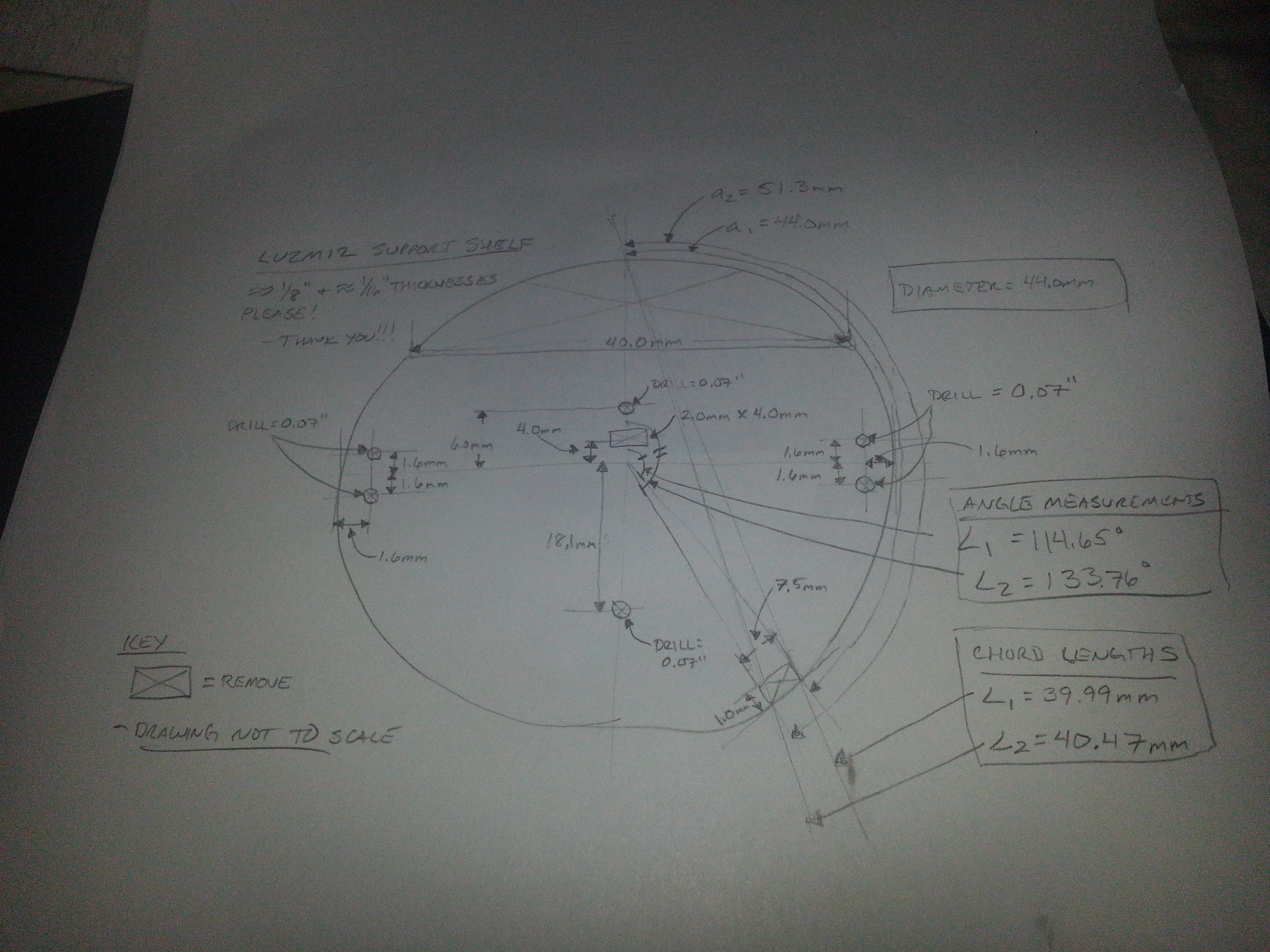
I coordinated with CtC concerning the acrylic disk. He has been more than helpful in this endeavor. Here's the diagram I sent him:
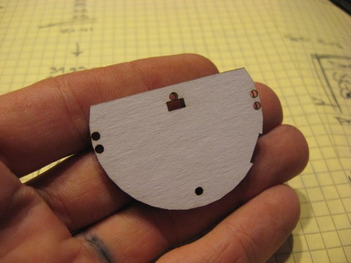
The pic he sent of the go/no-go test piece. I said, "Go!!!"
A look of how the disk will sit in the bot. The two holes running down the midline are for the servo mounts. The rectangle is to give a place for the servo cable to go. The standoff I'm using for the mounts won't leave enough room for the cable otherwise. The pairs of holes on the outside are for the disk mounts. I doubled up for stability and strength. The problem is...
I sent specs for #0 holes, not the #2 holes that I need :facepalm:
Chris said to send the revisions and he'll cut new pieces for me. What a guy. Still haven't sent the specs...
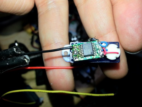
So anyhow, the SMD 08M2s came in and I figured it was time to get the PCB module up to speed.
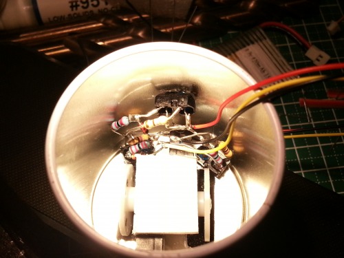
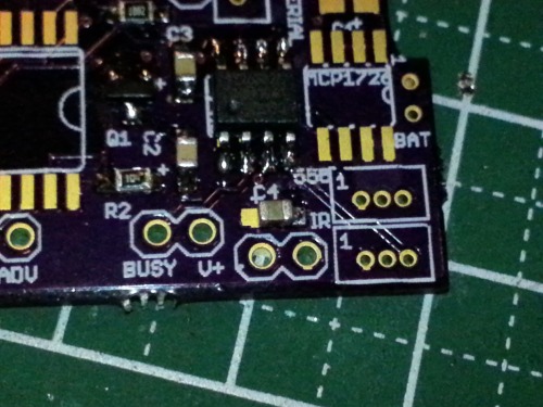
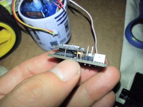
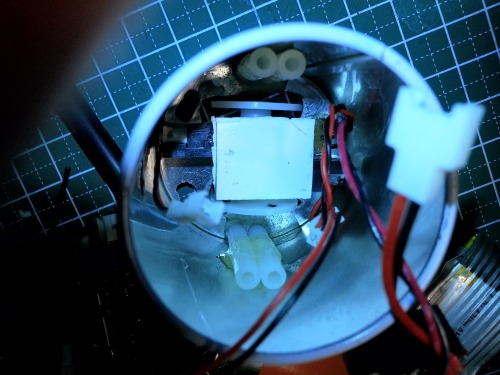
The PCB pretty much assembled minus some of the wiring harnesses.
The sound module rides above the L293DD chip with a small gap between them. The male header is for the serial programming/output selection. It looks monsterous next to its neighbors.
The PCB module riding inside with the most difficult connector attached. It looks like everything will clear! The 2.1mm jack will be for the lipo charger plug. There will be a programming jack for the PICAXE sitting next to it, I just haven't gotten to freeforming the resistors onto it just yet.
I'm trying to finish three bots for my robot rodeo at my work's craft fair that they have in the fall. I'm trying to make the November 15th deadline. It will be a feat to complete everything on time. I really want to have this robot in the mix, I'll be sad if it doesn't get finished in time.
UPDATE: Nov. 30th, 2012:
The bot did not get finished by the planned finish date. To be brief I bit off way more than I could chew and LU2MI2 was a major part of the lack of progress. On to the visuals...
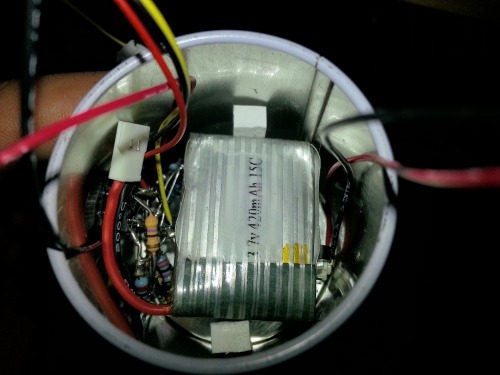
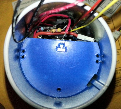
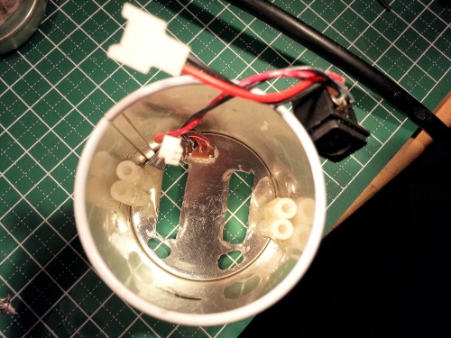
Updated pic of all the bits I need to cram into the main part of the bot's chassis.
I used some threaded and non-threaded standoffs to mount the acrylic disk in the bot. I used 2-ton epoxy to adhere them to the chassis.
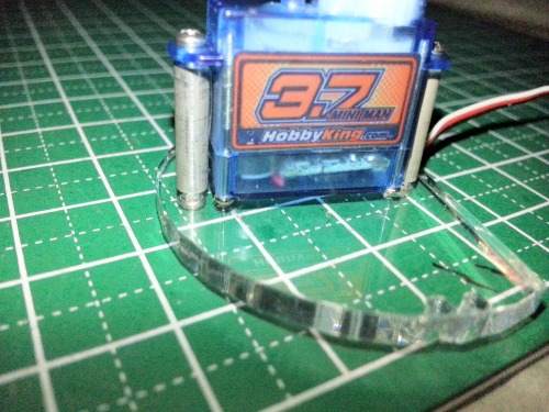
I found some other #0 sized standoffs that worked almost perfectly as servo mounts.
The 3.7g servo came with a standard sized 0.1" pitch connector that needed to be replaced with its micro-sized replacement.
The power switch and charging jack harness glued into the chassis.
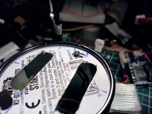
The switch lever was too long so it got the rotary tool treament to grind it down to size.
The 2.1mm charging jack with hotglue serving as insulation/strain relief.
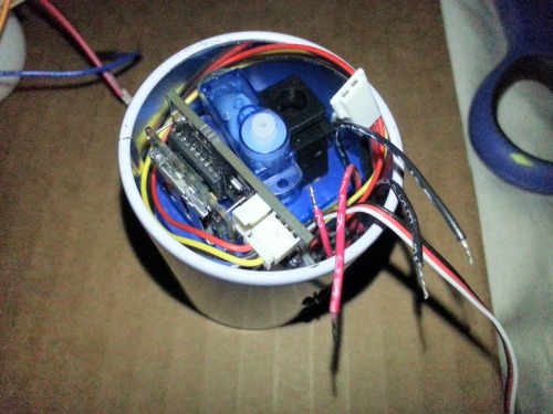
Motors wedged into position.
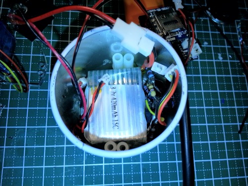
The majority of the components stuffed into the bot.
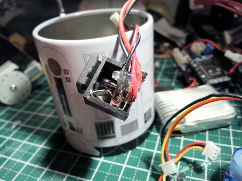
It was about this time that I decided to flip the power switch to see if I got any response. Well, I did, and the response was in the form of Magic Smoke. It turns out the only detail I needed to remember during assembly was the one I forgot. The patch cable that leads from the battery has reversed colored leads; the red is GND and the black is V+. Hence the smoke. So after that I had to totally refabricate the switch and charging jack assembly which, for some reason, was much more time consuming the second time around.
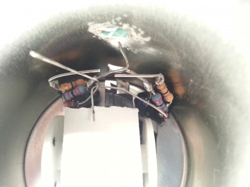
After that I turned my attentions to the head mounted circuitry:
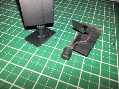
The RGB LED and phototransistor used in the head circuit needed some painting. I masked the leads off with some cellophane tape and masked the faces off with double-sided foam tape. I shot the LED with white plastic primer first and then shot both the LED and phototransistor with black plastic primer.
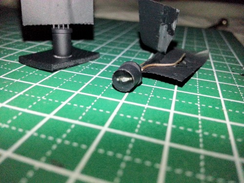
Closer look.
I populated the head PCB and mounted the phototransistor and the RGB LED in the head (no pics yet, sorry). After some manual testing of the head on the bot I found that some of the components interfere with some parts mounted in the main part of the bot. The harnesses to the PT and LED are too short to reposition the PCB into a better position so those will need to be redone.
I've got a lot (probably too many) plates spinning and this is considered a recreational project so it might take a back seat to a couple pressing issues.
Fear not, lumi... the bot is merely a sojourner on the sidelines and will eventually crawl out of the droid factory :)
Travel in pockets, live on desks, play snooker once in awhile
- Actuators / output devices: 2x tiny gear motors
- Control method: Full autonomous
- CPU: PICAXE 08M2
- Power source: 3.7V LiPo minature helicopter battery
- Sensors / input devices: Forward IR reflective sensor, two more underneath
- Target environment: indoors, flat surfaces
This is a companion discussion topic for the original entry at https://community.robotshop.com/robots/show/lu2mi2

 … collected…
