I have two brand new LSS-HT1 servos and an LSS controller card with 6 ports. I followed the instructions to a T.
XT60 connected to 12V
USB connected to PC on COM4 (by the way, the USB connector you use is ancient - it is hard to find cables)
Switch selected to USB
Motor connected to JP1.
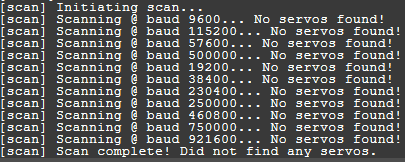
When I hit “SCAN”, choose all servos and all baud rates, it goes through each baud rate and says “No servos found!” and in the end it says “Scan complete! Did not find any servos.”
I tried both LSS-None-(???—K) and LSS All (254; --k) options, same result.
I tried the second brand new motor, same result.
When I click the FIRMWARE button, it says the motor has the latest firmware from 07-April-2020.
To confirm, according to the guide for the LSS Adapter:
" The two XBEE to USB jumpers do NOT need to be in place in any communication mode except for the “USB Explorer” feature. The intended uses include:"
Can you remove both of them and try again?
The two XBEE to USB jumpers do NOT need to be in place in any communication mode except for the “USB Explorer” feature.
is confusing and ambiguous. Perhaps an explicit line that “servos won’t be recognized for configuration if the jumpers are present.” would help.
What do I do to make it behave like a traditional servo? Like “home” at 0 degrees and movement of -90 to +90 degrees? The gyr direction can only be CW or CCW and not omni. Do I use the origin offset to 900?
Since I will never be using these for RC, can I leave the jumpers off permanently?
Q) What do I do to make it behave like a traditional servo? Like “home” at 0 degrees and movement of -90 to +90 degrees?
For standard 180 degree travel (-90 to +90), the AR (Angular Range) command is used. Unless you modified the origin offset, it should be at the same angle as most other RC servos. #0AR1800\r
(assuming servo ID is zero)
If you want to write this to memory so this is retained every time: #0CAR1800\r
Note that you don’t need to send the action command and can send the configuration command directly.
Q) The gyre direction can only be CW or CCW and not omni.
The gyre direction is just the direction the servo travels based on angular input. It cannot be omni since that would mean there are two identical angles at all times.
Q) Do I use the origin offset to 900?
Correct. If you want the zero of the servo to be offset by 90.0 degrees, yes, the command would be: #0O900\r
(assuming servo ID is zero)
If you want to write this to memory so this is retained every time: #C0O900\r
If you’re able to define a baud rate and use the serial output command, you’re pretty well set up to use the LSS protocol directly and don’t necessarily need the library.
As @cbenson mentioned, you can use O and CO to set the origin (or offset) of the LSS. If used without a value, O/CO will use the current position as a zero. Please note that if your virtual angle is < -180° or larger than 180° during a power cycle, the angle when starting will be set to a value in the range of [-180°, 180°].
Using the O/CO commands will update variables “live” and you can keep using your servo without a reset.
As for CW/CCW, the G/CG commands only change which direction are the positive & negative direction of the angle. You can always move in both direction using D (move to absolute position) and MD (move to relative position, a delta) commands.
One more question - I am using an Arduino Mega 2560 which has 4 hardware serial ports. Can I use any of them (in pair) for the LSS Adapter or does LSS insist on Pin 0 and Pin 1? I would think LSS would be blind to where the data is coming from/going to correct?
No problem!
I’m watching on a few sections and tags, so I usually at least read most LSS posts… But, if you make a new topic and need help related to the libraries or software, feel free to @ me and I’ll answer when I can.
Indeed it does!
In theory - and from a software point of view - any of them can be used with the Arduino LSS library (it can use any serial objects, including SoftwareSerial ones!).
The bus is hard-wired to the single hardware serial port of the regular Arduino board design, thus pin 0 & 1.
That being said, there are a few options you can go for, such as:
Check the wiki for the LSS Adapter Board, section Arduino under Software Serial and Stacking
Pins D8 & D9 of the Arduino are also connected to the bus when the switch is in Arduino mode (and XBee mode).
Connect some jumper wires from TX1/RX1 (or 2, 3) to D8, D9.
Setup the appropriate serial port in the code instead of the default serial interface. Then, don’t use D8/D9 for anything (to prevent conflicts). Shouldn’t be too difficult since the Arduino Mega 2560 has a lot of GPIOs anyway (minor understatement… ).
I know about the options on an Arduino Uno. I was specifically asking for Arduino Mega. Can any of the UARTs on the Mega be used to drive the LSS Adapter board instead of the standard Tx Dx pins?
My answer is about the Mega specifically.
Whether it is the Uno or Mega, they both have the same headers for the shield compatibility.
The solution is to use jumper wires to connect the GPIOs of the hardware serial port of your choice to D8 & D9 on the LSS Adapter Board to connect the LSS bus and that hardware serial port together.
As said above, the steps are:
Connect pins D8 & D9 of the Arduino (Uno or Mega) to the LSS bus by placing the LSS Adapter Board’s communication switch in Arduino mode.
Connect jumpers wires from TXn/RXn of the hardware serial port of your choice (where n=1, 2 or 3;) [On the Arduino Mega headers] to the D8 & D9 pins [on the LSS Adapter Board].
In the code, initialize the corresponding hardware serial port used above and pass that to your LSS object. Note: Do not use D8 & D9 for anything in the code, since that would certainly likely conflict with the use of the LSS bus.
Those are the pins that are the alternative to using D0/D1.
If you read this section (and also this section) you will note that D0/D1 are hard wired in the LSS Adapter Board circuit (traces on the PCB) to the LSS bus (through a buffer). Also, D8/D9 are also similarly hardwired to the LSS bus, too, but only when the communication switch is in Arduino mode.
Concerning the circuit itself/PCB/wiring, you can ask more details from @bdaouas.
Since the LSS Adapter Board works as a shield if it is connected to the Arduino Mega 2560 directly (placed on top of it like a shield) those hardwired connections will take effect.
A possible alternative option is to not place the LSS Adapter Board directly on the Arduino Mega 2560 but instead place it beside it. With all electronics powered off (double check! ), use jumper wires to connect your Arduino Mega 2560 to the LSS Adapter Board. At minimum, you will need a common GND connection and the relevant TX/RX pair for your chosen hardware serial port.
For example, following this idea, if you want to use the hardware serial port 1 you’d wire TX1/RX1/GND headers from the Arduino Mega 2560 to the LSS Adapter Board TX/RX/GND headers using jumper wires.
Again, @bdaouas can offer some more details here for the electrical stuff if needed.
ok - that makes sense. I was not planning to stack them anyway (i.e. use the LSS as a shield) … the LSS will power two motors in my robot and there are other boards that will power the rest of the motors.
Initially, for easy visualization and debugging, all the boards will be mounted side by side on a non-conductive platform with assorted breadboards.
Hi , we just bought a new lynxmotion 5DOF robotic arm with LSS adapter and servos HT-1 and ST-1, i have download the LSS Config Software but the servos cannot be found when it scanned. can u help me what should i do?
note:
1.i have also updated the firmware and the servo blink and goes to blue led and firmware is sucesfully update.
2. I have removed the jumper
but still can not find servo
If you were able to update the firmware, the LSS Adapter’s switch is likely set to USB mode which does not need to change. That also means the wall adapter’s ON/OFF switch was set correctly.
Once all servos have unique IDs, you can scan the bus and hopefully it will work.
If that doesn’t work, which version of the firmware did you upload? The servo’s LED should not stay blue after it has gone through the startup process unless you specifically selected that color to remain ON (via CLED = configure LED command).
The config software can not find the servo even only one servo connected… so i cant not set the ID, when the firmware update in progress. the servo blue led is on, and when the update is complete all led is off.