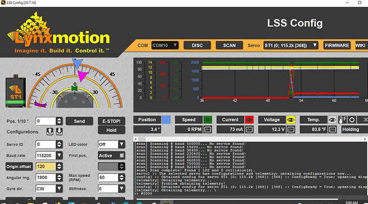
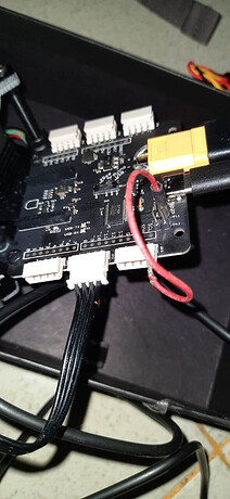
I Just Found the following WIKI
https://wiki.lynxmotion.com/info/wiki/lynxmotion/view/lynxmotion-smart-servo/lss-button-menu/
is it possible the problem is my servo is on RC mode? but i dont understand what is the meaning of button menu which is used to change the servo mode. there is no button / push button in the LSS adapter board or in the servo. and i have tried the 5v to the servo’s rx pin for 30s, the red led blink once… but still can not find servos
Did you ever press the button? If so, then yes, you may have changed the mode.
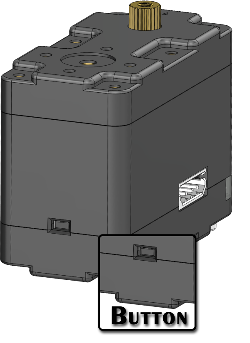
Yes, there is a button at the center rear of the servo (opposite the LED). If you did not press that before, then the stock servo is in serial mode, and you would not have been able to flash new firmware.
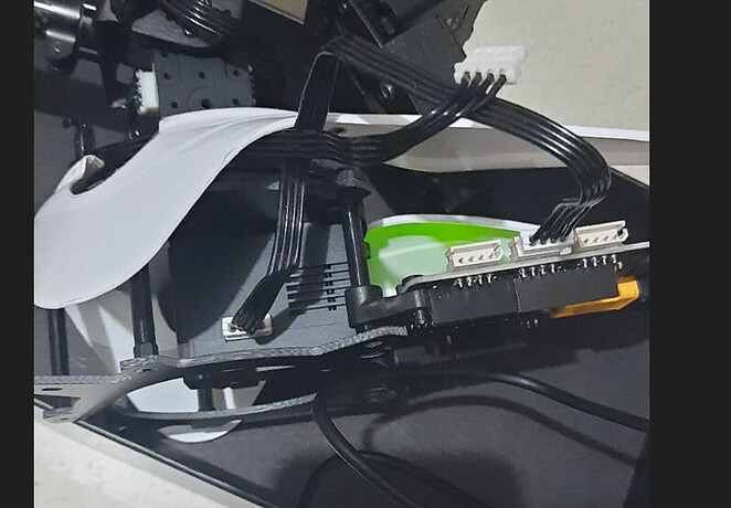
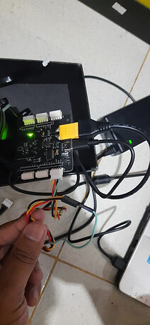
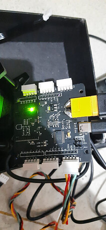
Can you take a few clear photos of your setup?
I just realized that button, i never touch it before , but i dont know if the seller of this robot had pressed the button, because the arm robot had been assembled when it arrived.
what should i do next?
The factory reset has been done, but the servo still can not be found. i had servo tester arduino and test the servo, but the servo didnot move,
and I monitored the usb-rx led when updating the firmware, is it normal that the led doesn’t light up at all when the update process in progress?
What we were ideally looking for (with a photo of the top of the LSS Adapter) are:
- Is the switch set to USB. Verify it’s all the way to the end as opposed to partway there. LSS - Adapter Board (USB Mini) - XWiki
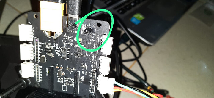
- The jumpers don’t need to be in place (they are shipped not connected).
- Is the Wall Adapter set to ON (switch on the cable)
- Ensure the board is properly recognized by the computer. If you have an LSS Adapter board with micro B, download the FTDI VCP Driver for your operating system. If your LSS Adapter uses a USB type C, then you need to download and install the CH430 drivers.
i try to read the lss tx data but there is no data send, and also i test the loop back tx to rx and read using serial terminal but there is no data available.
loopback using the following jumper it works
i think the problem is serial data not send using the xt5 pin
when i using rx pin from that jumper, it works
is this the hardware faulty or i missed something?
Note that you should not have the jumpers in place (those are for a wireless Bee module, which you don’t have). Wiring for the arm is normall incredibly straightforward.
- LSS Adapter Board set to USB (seems to be the case, but please move it away and back to the USB position to be sure)
- Power supply connected corrected and set to ON (seems to be the case)
- FTDI VCP drivers installed correctly - seems to be OK
- No jumpers in place
- ONE servo connected to one of the six pins
- Open the LSS Config software and SCAN for servos
- Servo in serial mode (seems to be the case, with servo ID 0)
Don’t use any other cables (only the black one). If one servo is not detected, try another, then another (to narrow down the issue to the LSS Adapter itself).
You said you were able to flash “New firmware” to the servos? How did you do that if the servos were not detected? Which firmware did you flash and how?


