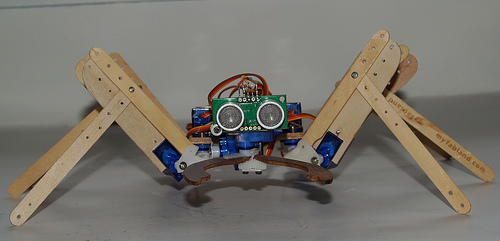
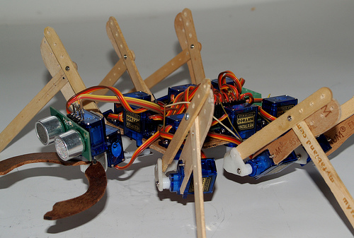
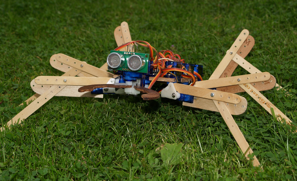
Lollypod

Hi guys,

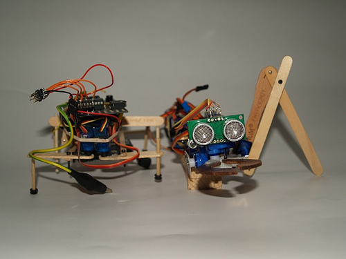
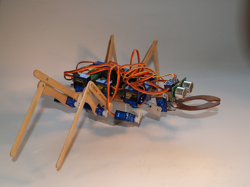
Thought it was about time I posted, this is actually my second robot. My first can be seen in some of the pics beside Lollypod. It used an 18x project board with SRF05 (now robbed for Lollypod) to work the three servo hexapod design. It worked pretty well but the frame was a bit too flexible which threw off the gait, plus I was using mismatched servos. Anyway it got my programming started and I may rebuild it at some point.

After that, I went ahead and ordered a load of dirt-cheap micro servos for a more advanced prototype :) . I wanted to spend as little as possible on materials so I went for lolly sticks as my sister gets through about one a day. They're a pretty good shape and size for robot parts. Apart from that it used some thin aluminium sheet and random screws and bolts.
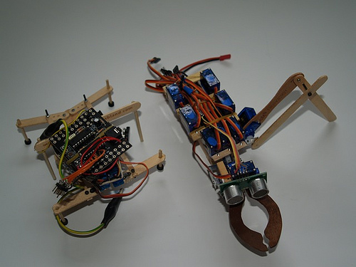
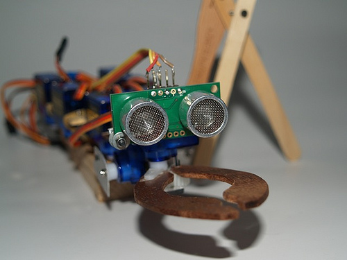
NeckJaws

More to come!


Update 13/7


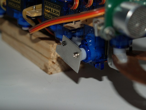
Done a good bit of work on Lollypod and it's changed a good bit! I'll start with the legs. Originally I was using an aluminium bracket to join the two servos of each leg together. This wasn't ideal because


  • It meant the two servos were offset, making the leg less compact and meaning it needed more clearance to get a decent range of movement.
  • I didn't have enough tiny screws to attach the servo arms to the bracket.
  • I wanted to play with polymorph.


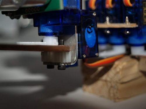
So instead I got ahold of some polymorph and started figuring out how to make this tricky part. At first I wanted to make the servo output shaft fit straight into the polymorph and eliminate the servo arms, but unfortunately the polymorph just didn't mould well enough to give a tight fit and the shaft could easily slip. So instead I made the polymorph fit around the servo arms which allowed me to have a tight fit to the servos while also keeping the legs nice and compact. This did mean I had to use longer screws in the servo shafts but this wasn't a major problem. The brackets were made by cutting out a shape from a sheet of polymorph, drilling holes in the right places and folding it 90º along a score in the polymorph.The servo arms were then screwed temporarily in place while the bracket was heated and more polymorph was added, keying the servo arms in place and giving reinforcement.

Old bracket:
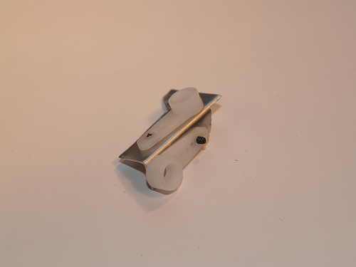
Old bracket

New bracket cut out, drilled and folded:
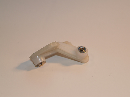
 

And finished.
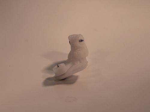
 

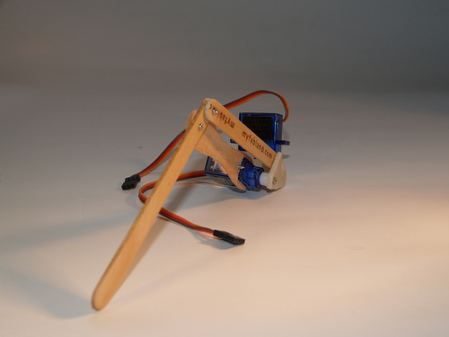
Here's the leg put together.
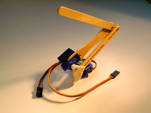
These leg brackets were the hardest part to make. I also had to change the body to give the legs some more clearance and make room for the servo controller. It's a plywood board which the servos and electronics bolt to. 15 servos make for a lot of cable!
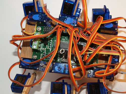
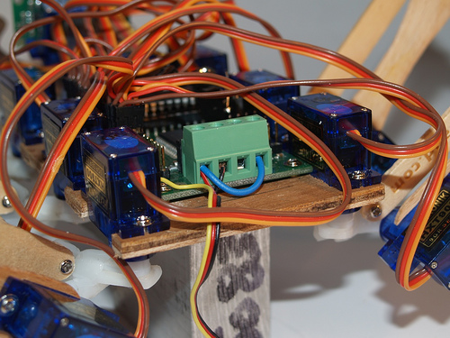
The servos I'm using are happy at 5V so I connected both the logic and servo supplies to my voltage regulator. Here's the terminal block showing the connections.
And here's the power wiring. I'm using a bigger battery than the one I had before simply because it had the right connector, but I might switch to the previous one to save on weight (44.4g vs 85.2g).
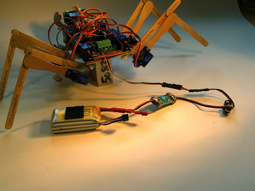
Now I need to get the front legs done and the mechanics will be complete. I'm going to do them slightly differently as I want to allow for a an extra servo per leg.


Update 14/7


Bit more about the brackets. I'm finished making them all now so I couldn't get any step-by-step photos, so I did some quick drawings instead. It's probably easier to see than the white plastic anyway.


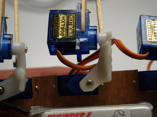
So I started by cutting out the polymorph sheet to the right shape. I worked out the shape by looking at the distance needed for clearance by each servo in each direction. I also added an offset which brought the outer servo forward to be in line with the inner, making the leg more compact. Basically, this makes up for the output shaft being around the middle of the servo when seen from below, and yet at the end of the servo when seen from the side. Here's a photo showing the offset.
And the range of movement I get from the outer servo.
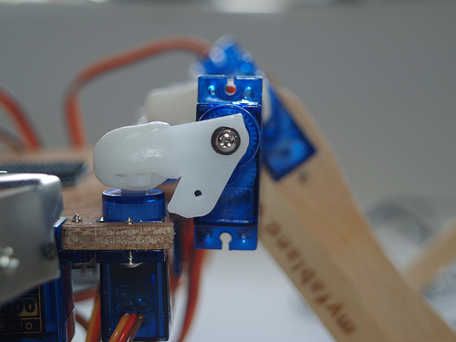
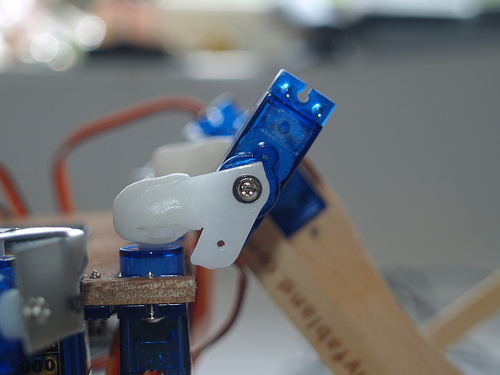
Here's the template I used to cut the bracket from the polymorph sheet.
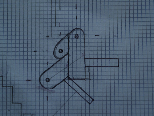
The long parts coming off were used to wrap around the servo arms, but in the end it was easier to just form a new lump around them instead so I stopped using them. Once this shape was cut out, I scored along where it needed to be folded.
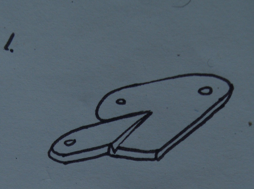
And then made the fold. Which way it was folded depended on which side of the robot the leg was destined for.
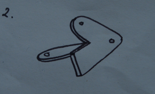
The next pic is just the bracket at the same stage, but turned over for a better look.
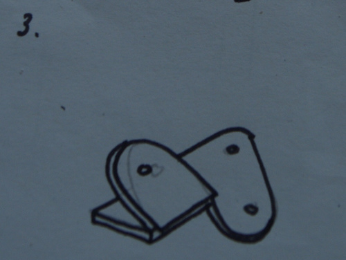
Next the servo arms are put on temporarily. These are hatched in red in the pic.

And finally extra polymorph was added to key in the servo arms, and reinforce the fold. This is blue in the pic.

The servo arms are actually kept on by the screws through the polymorph, them and the servo shaft. If the screws are taken out they slip out from under the polymorph. Hope this was helpful.


Update 16/7


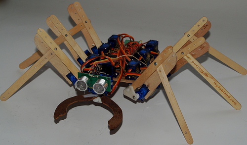
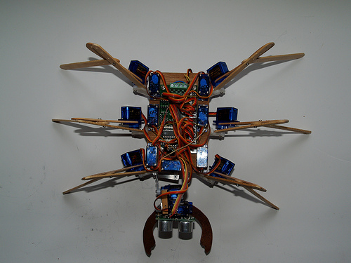
Okay I have the mechanics pretty much done. The two front legs got bolted on yesterday and then I spent some time playing with the code. I wanted it to be pretty flexible, ideally letting me alter variables, eg. body height and tilt, independently while walking. The SD21 servo controller makes this a bit easier as it has three sets of registers for the position of each servo, which can be used independantly by different parts of the code. I also drilled some extra holes in the legs to allow adjustment. Anyway heres some pics.


  • Control method: autonomous
  • CPU: 18X / SD21 servo controller
  • Sensors / input devices: SRF05

This is a companion discussion topic for the original entry at https://community.robotshop.com/robots/show/lollypod

neato!

Although I’m guilty of going for a space-age look a bit in my robots (?), I really like the resourcefulness here. I suppose it helps if you eat a lot of icecream.

Are you going for 2 servos for each leg? - what’s your dirt-cheap micro servo resource?

It looks very nice, if you
It looks very nice, if you ask me. hope the thing will walk soon. Guess you’re just waiting for your sister to eat more ice now :slight_smile:

Yup

Two servos per leg. I got twenty of these http://www.hobbycity.com/hobbycity/store/uh_viewItem.asp?idProduct=662 . $3.65 each.

We’re in the middle of a heat wave so lolly sticks are abundant!

I’m actually waiting on some polymorph so I can try making some custom servo arms, rather than the folded and bolted aluminium. This will also allow me to make the legs a bit more compact.

As far as i can see you have

As far as i can see you have 2 servos on each leg, hexapod has 6 legs, so you have 12 servos for the legs, Then you have something for the gripper in front as well. Each of these servos will draw pretty much current since its small and fast :slight_smile:

clipping from hobbycity.com

"There is a downside of beeing strong and fast, they draw quite a bit of current.
I measured about 550mA when exercising one HXT900 without load. This is an average, it seems to require more peak current. If used together with a linear BEC it will cause voltage drops."

I’m just curious on how you power this bot.what kind of batteries do you use?

That’s right, 2x6 servos for

That’s right, 2x6 servos for the legs plus one for the gripper and two for pan and tilt of the head, giving 15 in total. I’m planning on using a switching regulator, like this one; http://www.helidirect.com/castle-creations-10a-bec-switching-regulator-p-5159.hdx

I’m using an 850 mah lipo rated for 15c, giving 12.75 amps max discharge. Hopefully that’ll do the trick :slight_smile:

Sounds like a nice setup.

Sounds like a nice setup.

That will (theoretically, Q/i=time) give you like 6min run time with a constant discharge at 12.75 amps or more like 10min if we follow the suggestion from the comment from hobbycity.com.

Yeah, run times may be
Yeah, run times may be fairly limited. Hopefully I’ll get a bit longer than ten minutes as each servo will only be in motion around half the time, plus I probably won’t be moving them at full speed for normal walking around.

amazin

Great update - lots of info too.

Have you got it walking yet? i wonder what the result is like!

I’m RELLY keen to get more info on how you make the brackets - as you say, that seems the hardest part but I think I got a bit lost in one of the images.

You don’t have a 90 degree angle there right? are you worried about stressing the servo gears because of the long torque arm?

wowee, this is so cool!

hay
that were i get mine they also have an ebay store that give free postage!!

18x and sd21 controller?

18x and sd21 controller? That’s a really close set up to the big project i have in my mind! (really really close)

I’ll sure come back to you for some advices!

Good work, i’m waiting for a video…

Brackets

Hi emuller, no walking just yet as I have the front two legs to finish off. I’ve got it standing on its current four legs though. Regarding the brackets, yup they’re the tricky part, I’m going to add a bit more info about them.

I’m not quite sure which angle you mean - maybe the one between the inner part of the legs and vertical? This is really dictated by how high I want the body to be held, and the relative lengths of the inner and outer leg segments.

The outer leg part is held at a constant angle (approx 60º) to the vertical by the upper lollystick in the inner leg.

Totoro -

I’ve not really done much with the SD21 yet other than go through the servos and get them centered. I wrote a test program as well just to scan one of the legs back and forth and up and down - it’s pretty easy to get smooth movements using the servo speed registers.

"it’s pretty easy to get

"it’s pretty easy to get smooth movements using the servo speed registers."

How do you use those registers? The only example of code they give is :

symbol Servo1 = 63 ’ servo 1 base register
symbol Servo1p = 84 ’ servo 1 positive offset register
symbol Servo1n = 105 ’ servo 1 negative offset register
symbol Base = 128 ’ centre position symbol Offset = 50 ’ +/- 50 from centre position

ProgStart:
i2cslave $c2, i2cslow, i2cbyte ’ setup i2c port for servo controller
writei2c Servo1, (Base)
Loop:
writei2c Servo1p, (Offset)
pause 300
writei2c Servo1n, (Offset)
pause 300
goto Loop

but this code uses the second set of registers which seems to have no influence on the speed…

(and did you get my e-mail?)

Hi Totoro,You use the speed

Hi Totoro,

You use the speed registers in the same way, just by writing to the speed registers.


'defining speeds

for b0 = 3 to 57 step 3

writei2c b0, (speed)

next b0

Here I’ve just written the variable ‘speed’ to the registers which correspond to the speed of each servo.


Thanks!

Oh ok, that’s indeed really easy! I thought that it was some kind of parameter to pass to the function, like “writei2c b0, (offset), (speed)” but in fact you just set the speed you want for each servo and it keeps it until you decide to change…


That’s really cool!

Yes, finally a video! Looks
Yes, finally a video! Looks great, can’t wait to see it walking!!

Very creative
Good for going green and recycling. Wonder’s if it can carry it’s own weight in batterys. Bird has high respect for basement engineering.

RESPECT !!!12 servo for

RESPECT !!!

12 servo for locomotion is a lot of stuff, woody legs are the perfect touch, polymorph joints…

this is a serious 5 stars walker

Looks like you’ve forgotten
Looks like you’ve forgotten that there is basically no grip at the end of a lolly stick :slight_smile: slippery. But you’re robot just looks awesome. Looking forward to see it walk.

Thanks for the comments

Thanks for the comments guys. Actually the leg slippage is necessary when using 2 DOF legs, otherwise the servos would tear the legs off :).

While these legs do okay when the load is shared between all six, they aren’t really up to walking - the polymorph brackets are too flexible, amongst other things. So I’m going to redesign them for 3DOF. I’ll continue to use Lollypod and figure out how to add some sensors while I get the new leg parts made.