


Lollypod
Hi guys,
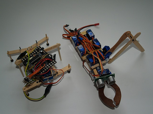
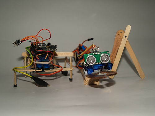
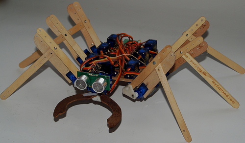
Thought it was about time I posted, this is actually my second robot. My first can be seen in some of the pics beside Lollypod. It used an 18x project board with SRF05 (now robbed for Lollypod) to work the three servo hexapod design. It worked pretty well but the frame was a bit too flexible which threw off the gait, plus I was using mismatched servos. Anyway it got my programming started and I may rebuild it at some point.
After that, I went ahead and ordered a load of dirt-cheap micro servos for a more advanced prototype :) . I wanted to spend as little as possible on materials so I went for lolly sticks as my sister gets through about one a day. They're a pretty good shape and size for robot parts. Apart from that it used some thin aluminium sheet and random screws and bolts.
More to come!
Update 13/7
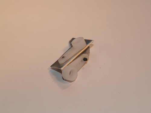
Done a good bit of work on Lollypod and it's changed a good bit! I'll start with the legs. Originally I was using an aluminium bracket to join the two servos of each leg together. This wasn't ideal because
- It meant the two servos were offset, making the leg less compact and meaning it needed more clearance to get a decent range of movement.
- I didn't have enough tiny screws to attach the servo arms to the bracket.
- I wanted to play with polymorph.
So instead I got ahold of some polymorph and started figuring out how to make this tricky part. At first I wanted to make the servo output shaft fit straight into the polymorph and eliminate the servo arms, but unfortunately the polymorph just didn't mould well enough to give a tight fit and the shaft could easily slip. So instead I made the polymorph fit around the servo arms which allowed me to have a tight fit to the servos while also keeping the legs nice and compact. This did mean I had to use longer screws in the servo shafts but this wasn't a major problem. The brackets were made by cutting out a shape from a sheet of polymorph, drilling holes in the right places and folding it 90º along a score in the polymorph.The servo arms were then screwed temporarily in place while the bracket was heated and more polymorph was added, keying the servo arms in place and giving reinforcement.
Old bracket:
New bracket cut out, drilled and folded:
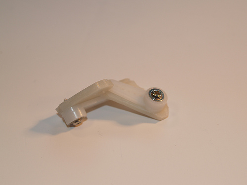
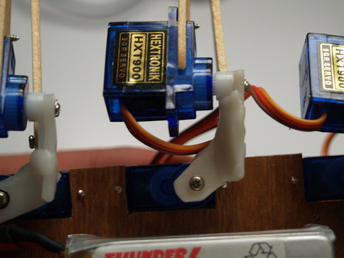
And finished.
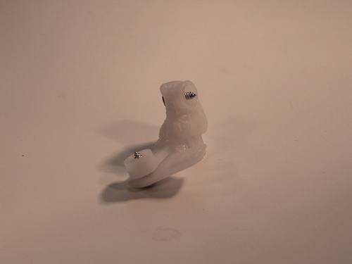
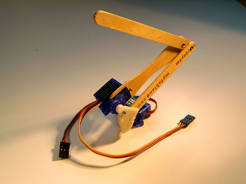
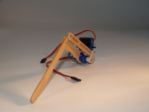
Here's the leg put together.
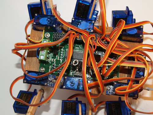
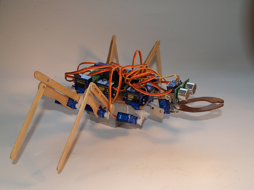
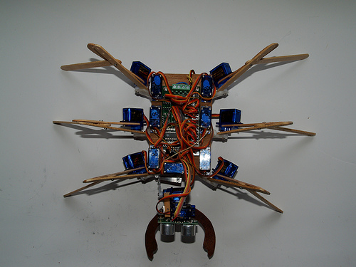
These leg brackets were the hardest part to make. I also had to change the body to give the legs some more clearance and make room for the servo controller. It's a plywood board which the servos and electronics bolt to. 15 servos make for a lot of cable!
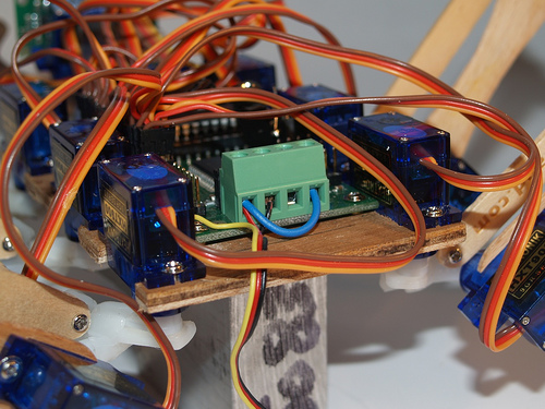
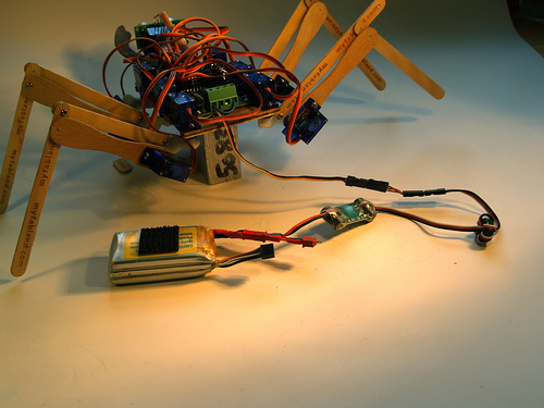
The servos I'm using are happy at 5V so I connected both the logic and servo supplies to my voltage regulator. Here's the terminal block showing the connections.
And here's the power wiring. I'm using a bigger battery than the one I had before simply because it had the right connector, but I might switch to the previous one to save on weight (44.4g vs 85.2g).
Now I need to get the front legs done and the mechanics will be complete. I'm going to do them slightly differently as I want to allow for a an extra servo per leg.
Update 14/7
Bit more about the brackets. I'm finished making them all now so I couldn't get any step-by-step photos, so I did some quick drawings instead. It's probably easier to see than the white plastic anyway.
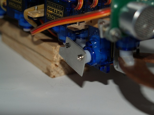
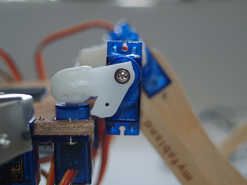
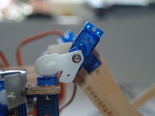
So I started by cutting out the polymorph sheet to the right shape. I worked out the shape by looking at the distance needed for clearance by each servo in each direction. I also added an offset which brought the outer servo forward to be in line with the inner, making the leg more compact. Basically, this makes up for the output shaft being around the middle of the servo when seen from below, and yet at the end of the servo when seen from the side. Here's a photo showing the offset.
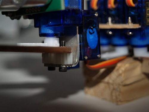
And the range of movement I get from the outer servo.
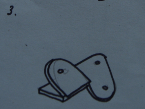
Here's the template I used to cut the bracket from the polymorph sheet.
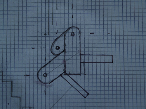
The long parts coming off were used to wrap around the servo arms, but in the end it was easier to just form a new lump around them instead so I stopped using them. Once this shape was cut out, I scored along where it needed to be folded.
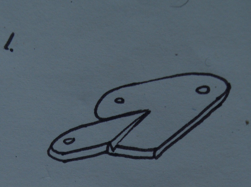
And then made the fold. Which way it was folded depended on which side of the robot the leg was destined for.
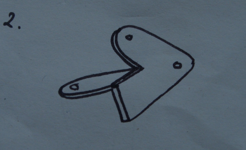
The next pic is just the bracket at the same stage, but turned over for a better look.
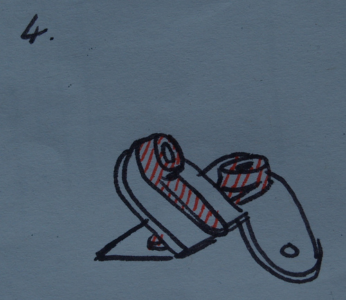
Next the servo arms are put on temporarily. These are hatched in red in the pic.
And finally extra polymorph was added to key in the servo arms, and reinforce the fold. This is blue in the pic.
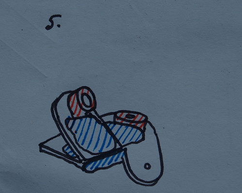
The servo arms are actually kept on by the screws through the polymorph, them and the servo shaft. If the screws are taken out they slip out from under the polymorph. Hope this was helpful.
Update 16/7
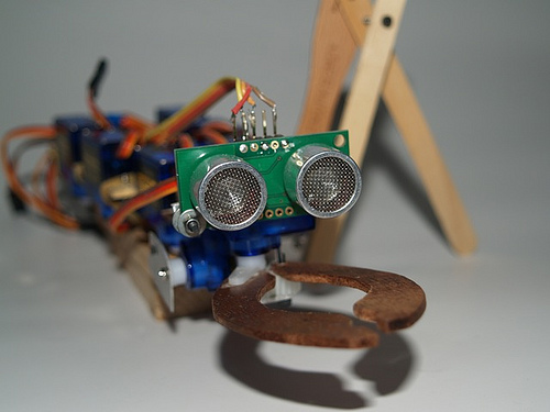
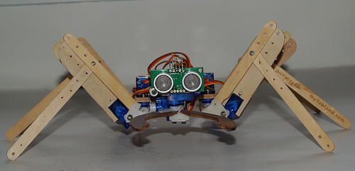
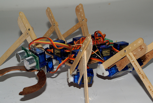
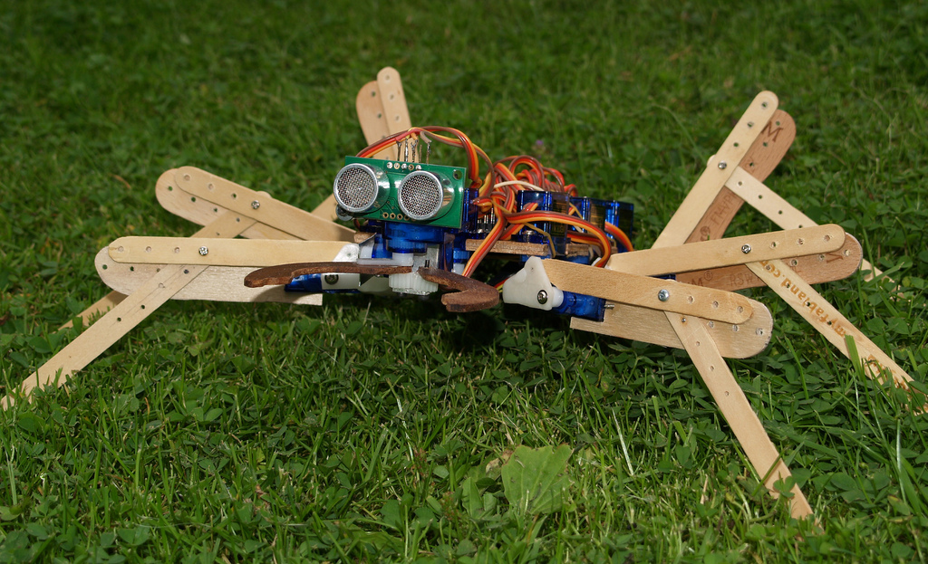
Okay I have the mechanics pretty much done. The two front legs got bolted on yesterday and then I spent some time playing with the code. I wanted it to be pretty flexible, ideally letting me alter variables, eg. body height and tilt, independently while walking. The SD21 servo controller makes this a bit easier as it has three sets of registers for the position of each servo, which can be used independantly by different parts of the code. I also drilled some extra holes in the legs to allow adjustment. Anyway heres some pics.
- Control method: autonomous
- CPU: 18X / SD21 servo controller
- Sensors / input devices: SRF05