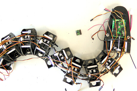
Hi @cbenson and @cmackenzie! Thanks so much for your replies. My project is being logged here: https://hackaday.io/project/176822-love-elemental – it’s a serpentine ROS-driven robot, although I haven’t yet started working on the fur & touch system, so it’s all skeletons and simulations at the moment. I’m using an interesting 2DOF spine joint design that uses a universal joint on the spine and 2 pushrod-based abdominal muscles, which is hopefully visible in the video.
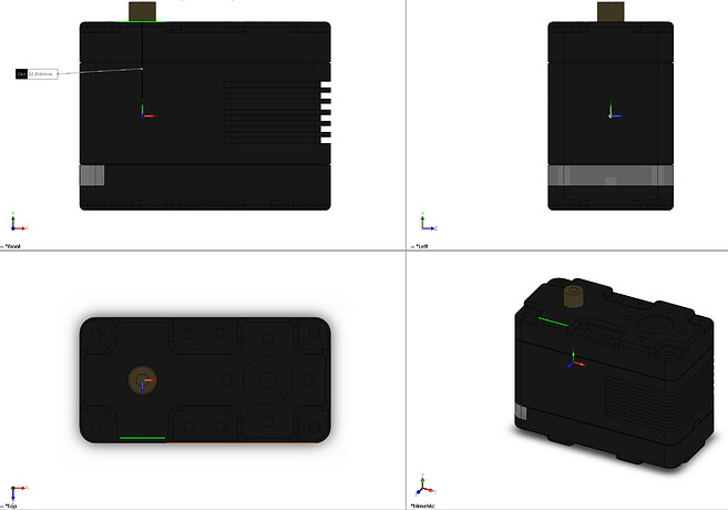
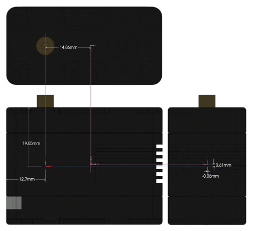
@cmackenzie, that’s really great that you have the tensor value(s)! I’m really glad that you’re gone to the trouble of weighing and approximating the structure of the servo to get a reasonable tensor approximation. If you don’t feel like reading what I wrote below, all I’d like is the 9 inertial tensor floats with 3+ digits of precision, and the 6DOF center of mass (3 xyz, 3 rpy; or quaternions or whatever you’ve got, lol) they’re based on in some servo casing-relative coordinate system.
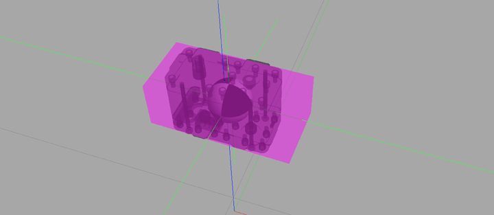
I’m actually doing the CAD in a custom & purpose-built system I’ve created in Python. It unifies OpenSCAD (for 3d printed part design), FreeCAD (for importing STP files from various hardware vendors), Meshlab (for inertial tensor estimation and STL measurement integration), xacro (because advanced sensors in ROS/Gazebo require xacro to instantiate), and it simultaneously generates an OpenSCAD-based preview, a URDF/SDF model (since I need to use 4-bar linkages that aren’t expressable in URDF but are simulatable in Gazebo, along with Gazebo-compatible meshes for visualization), individual parts for 3d printing, and a smattering of other files to get actuator PID simulation running out-of-the-box. Since it’s all programmatic, constraints and tweaks are easy to apply to regenerate the dozens of files needed to get ROS & Gazebo running. My CAD environment also has concepts of attachment points for parts and local part orientations, so that I can model screw holes in STP & STL files, and then have parts “snap” together as I build the robot in the live-editing workflow.
As an example, here’s the code I use to model the LSS Servo (sorry for all the magic constants; there’s so many vendors I’m finding parts from, and I’m planning to release all this with the “parts library”, since maybe others will want to build & simulate robots with semiaccurate physics and 3d printing):
def lss_servo(id):
    """
    Create an LSS HT-1 servo
    """
    attachment_points = {}
    link_name = f'servo_{id}'
    script = compute_mesh_geometry('/home/dgrnbrg/catkin_ws/src/love_elemental_description/meshes/LSS-Public.stl', merge_close_vertices=True)
    bounding_box_min = script.geometry['aabb_min']
    bounding_box_max = script.geometry['aabb_max']
    bounding_box_offset = [-(x+y)/2.0 for (x,y) in zip(bounding_box_max, bounding_box_min)]
    # correction for the servo horn being included in the bounding box, derived by trial and error :(
    bounding_box_offset[1] += 2.01
    orientation_xf = Transform(rot=(90,0,0)).compose(Transform(xyz=bounding_box_offset))
    attachment_points['center'] = Transform()
    # up by half the height, offset by one quarter the length
    attachment_points['output_gear'] = Transform(xyz=(-50.8/4.0,0,38.1/2.0))
    attachment_points['left_wide_bracket'] = Transform(xyz=(0,25.4/2,0), rot=(-90,0,0))
    attachment_points['right_wide_bracket'] = Transform(xyz=(0,-25.4/2,0), rot=(90,180,0))
    attachment_points['left_narrow_bracket_idler'] = Transform(xyz=(50.8/4,25.4/2,0), rot=(-90,0,0))
    attachment_points['left_narrow_bracket_output'] = Transform(xyz=(-50.8/4,25.4/2,0), rot=(-90,0,0))
    attachment_points['right_narrow_bracket_idler'] = Transform(xyz=(50.8/4,-25.4/2,0), rot=(90,180,0))
    attachment_points['right_narrow_bracket_output'] = Transform(xyz=(-50.8/4,-25.4/2,0), rot=(90,180,0))
    def scad_render():
        return orientation_xf.to_solid_xf()(so.color((0.2,0.2,0.2), alpha=0.5)(s.import_('/home/dgrnbrg/catkin_ws/src/love_elemental_description/meshes/LSS-Public.stl')))
    part = None
    def urdf_render(from_joint):
        gazebo_extras = f"""
          <gazebo reference="{ link_name}">
            <material>Gazebo/Black</material>
          </gazebo>
        """
        self_mesh = '/home/dgrnbrg/catkin_ws/src/love_elemental_description/meshes/LSS-Public.stl'
        # TODO the servo's mesh is not watertight, and simple approaches in meshlab aren't helping
        return scad_to_urdf(from_joint=from_joint, part=part, gazebo_extras=gazebo_extras, scad=None, stl_path=self_mesh, mass=cfg.lss_ht.mass, merge_close_vertices=True)
    part = Part(link_name=link_name, attachment_points=attachment_points, scad_render=scad_render, urdf_render=urdf_render)
    return part
Usually, the utility function scad_to_urdf handles estimating the inertial tensor based on mass or density info, plus a model of the part. In this case, if you either had the unit-mass inertial tensor or the actual-mass-scaled inertial tensor as a simple list ([[. . .],[. . .],[. . .]]) and the center of mass, I can just plumb that through my system. Is that similar to the way that you derive & consume it in Gazebo?


