Inertial Tensors for HT and ST LSS servos?

Hello, I am trying to make a rudimentary simulation that uses these actuators, to help me develop some parts of my robot without building everything first. I’ve been using the CAD models of the LSS you provide, which are great, but I’d like a better inertial tensor for the actuator than what I can compute. For me, I can only weigh the servos, do some mesh repairs to make it watertight, and then use Meshlab to compute the inertial tensor. Of course, this is wildly incorrect, because it doesn’t factor in the densities or arrangements of the gears and motors inside the servo.

Would it be possible for you to export from your internal cad an inertial tensor & center of mass for the actuator? If you can’t generate an inertial tensor, could you suggest a simplified model that I could use to estimate the inertial tensor (i.e. maybe the motor, 1-2 gears as cylinders, and the case with their relative center of mass offsets)? I don’t need a precise measurement, but I’d like to capture the lopsidedness of the servo internals while modeling the motion.

I’d be happy to share more about my hobby robot here or over email if that would help! The very short version is that I’m modeling the robot in GazeboSim as well as IRL to help me develop the kinematics without breaking parts :slight_smile:

1 Like

@dsg123456789 You might want to get in contact with @cmackenzie who has also modeled these servos quite well. Yes, we’re certainly curious about your robot project. Can you describe it more? Why not share here as opposed to email? Posting here might get others interested as well. If it’s a bit confidential, or you have other reasons, you can PM me here.

As you can see in the first video, getting these values accurate is important or else the robot dances:

You can see the progress here:

@raess is also working in ROS for his K3lso project:

Hi @dsg123456789,

I can get you the tensor values you are looking for. I was in touch with one of the RobotShop designers and we used a process of weighing internal components and his full internal CAD model to generate it. What CAD package are you using? Solidworks? Unfortunately, my computer’s power supply died and a new one comes in tomorrow so once I get it back up I can get those values for you. Can you explain more about what type of robot you are simulating?

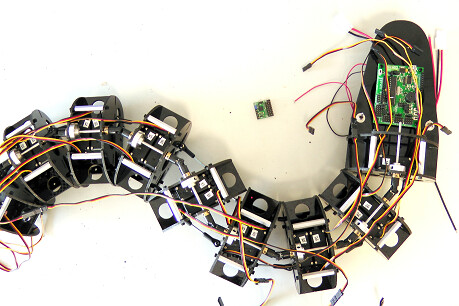
Hi @cbenson and @cmackenzie! Thanks so much for your replies. My project is being logged here: https://hackaday.io/project/176822-love-elemental – it’s a serpentine ROS-driven robot, although I haven’t yet started working on the fur & touch system, so it’s all skeletons and simulations at the moment. I’m using an interesting 2DOF spine joint design that uses a universal joint on the spine and 2 pushrod-based abdominal muscles, which is hopefully visible in the video.

@cmackenzie, that’s really great that you have the tensor value(s)! I’m really glad that you’re gone to the trouble of weighing and approximating the structure of the servo to get a reasonable tensor approximation. If you don’t feel like reading what I wrote below, all I’d like is the 9 inertial tensor floats with 3+ digits of precision, and the 6DOF center of mass (3 xyz, 3 rpy; or quaternions or whatever you’ve got, lol) they’re based on in some servo casing-relative coordinate system.

I’m actually doing the CAD in a custom & purpose-built system I’ve created in Python. It unifies OpenSCAD (for 3d printed part design), FreeCAD (for importing STP files from various hardware vendors), Meshlab (for inertial tensor estimation and STL measurement integration), xacro (because advanced sensors in ROS/Gazebo require xacro to instantiate), and it simultaneously generates an OpenSCAD-based preview, a URDF/SDF model (since I need to use 4-bar linkages that aren’t expressable in URDF but are simulatable in Gazebo, along with Gazebo-compatible meshes for visualization), individual parts for 3d printing, and a smattering of other files to get actuator PID simulation running out-of-the-box. Since it’s all programmatic, constraints and tweaks are easy to apply to regenerate the dozens of files needed to get ROS & Gazebo running. My CAD environment also has concepts of attachment points for parts and local part orientations, so that I can model screw holes in STP & STL files, and then have parts “snap” together as I build the robot in the live-editing workflow.

As an example, here’s the code I use to model the LSS Servo (sorry for all the magic constants; there’s so many vendors I’m finding parts from, and I’m planning to release all this with the “parts library”, since maybe others will want to build & simulate robots with semiaccurate physics and 3d printing):

def lss_servo(id):
    """
    Create an LSS HT-1 servo
    """
    attachment_points = {} 
    link_name = f'servo_{id}'
    script = compute_mesh_geometry('/home/dgrnbrg/catkin_ws/src/love_elemental_description/meshes/LSS-Public.stl', merge_close_vertices=True)
    bounding_box_min = script.geometry['aabb_min']
    bounding_box_max = script.geometry['aabb_max']
    bounding_box_offset = [-(x+y)/2.0 for (x,y) in zip(bounding_box_max, bounding_box_min)]
    # correction for the servo horn being included in the bounding box, derived by trial and error :(
    bounding_box_offset[1] += 2.01
    orientation_xf = Transform(rot=(90,0,0)).compose(Transform(xyz=bounding_box_offset))
    attachment_points['center'] = Transform() 
    # up by half the height, offset by one quarter the length
    attachment_points['output_gear'] = Transform(xyz=(-50.8/4.0,0,38.1/2.0))
    attachment_points['left_wide_bracket'] = Transform(xyz=(0,25.4/2,0), rot=(-90,0,0))
    attachment_points['right_wide_bracket'] = Transform(xyz=(0,-25.4/2,0), rot=(90,180,0))
    attachment_points['left_narrow_bracket_idler'] = Transform(xyz=(50.8/4,25.4/2,0), rot=(-90,0,0))
    attachment_points['left_narrow_bracket_output'] = Transform(xyz=(-50.8/4,25.4/2,0), rot=(-90,0,0))
    attachment_points['right_narrow_bracket_idler'] = Transform(xyz=(50.8/4,-25.4/2,0), rot=(90,180,0))
    attachment_points['right_narrow_bracket_output'] = Transform(xyz=(-50.8/4,-25.4/2,0), rot=(90,180,0))
    def scad_render():
        return orientation_xf.to_solid_xf()(so.color((0.2,0.2,0.2), alpha=0.5)(s.import_('/home/dgrnbrg/catkin_ws/src/love_elemental_description/meshes/LSS-Public.stl')))
    part = None
    def urdf_render(from_joint):
        gazebo_extras = f"""
          <gazebo reference="{ link_name}">
            <material>Gazebo/Black</material>
          </gazebo>
        """
        self_mesh = '/home/dgrnbrg/catkin_ws/src/love_elemental_description/meshes/LSS-Public.stl'
        # TODO the servo's mesh is not watertight, and simple approaches in meshlab aren't helping
        return scad_to_urdf(from_joint=from_joint, part=part, gazebo_extras=gazebo_extras, scad=None, stl_path=self_mesh, mass=cfg.lss_ht.mass, merge_close_vertices=True)
    part = Part(link_name=link_name, attachment_points=attachment_points, scad_render=scad_render, urdf_render=urdf_render)
    return part

Usually, the utility function scad_to_urdf handles estimating the inertial tensor based on mass or density info, plus a model of the part. In this case, if you either had the unit-mass inertial tensor or the actual-mass-scaled inertial tensor as a simple list ([[. . .],[. . .],[. . .]]) and the center of mass, I can just plumb that through my system. Is that similar to the way that you derive & consume it in Gazebo?

Very interesting project and I wish I had previous prototypes to take photos (barely even remember where the CAD might be), but we had created a snake-like prototype which looks almost identical to what you’re developing (using normal RC servos at the time). The backbone use universal joints, and the plates (what you have in black) were carbon fiber. The connecting rods can be found below as well:

Friction between your “snake” and the surface will be a significant source of friction, so watch out for that part of the project. You might also save a bit of weight and cost by using two servos for every ~3 sections rather than having two servos per section, without much loss in motion or functionality.

1 Like

That’s really cool that you built one too! I’ll be sure to post updates here, since I’ve mostly sourced the parts now and just need to print and assemble the first skeleton prototype. This robot actually uses wheels to “skate”, so it has a different mode of motion than robots with equal friction coefficients in every direction.

image

2 Likes

Hi @dsg123456789. Really awesome looking project. I am also particularly interested in how you are generating your robot models programmatically. I am very familiar with xacro and I’ve used FreeCAD, heard of OpenSCAD but I havent used it (directly). The legged robots I am working on are part of a full erector set of pieces and I’ve also been mulling around how a less experienced user could build their custom design and create the URDF they need for physical control and simulation. I used Solidworks and a lot of hand crafted URDF since Solidworks URDF export is very buggy but I can’t expect many will get through this hurdle. In Solidworks we also have attachment points so I was thinking along the same lines as you. If the erector parts contained XYZ-RPY points as part of the model some kind of software could be used to describe the linkages much easier, then output a URDF with fixed parts pre-combined and calculated inertias. So no question, what you are doing is AWESOME. Could you possibly release this as OSS? I would joint the project and help out for sure. The one thing I couldnt settle on was what kind of UI would work. I wanted something more like the Lego designer which is very simple drag and drop of existing parts. I’ve had some trouble with FreeCAD, it’s looking good, but still buggy. A FreeCAD workbench extension that adds this stuff would be nice. I was also considering just doing it directly in RViz2 with visuals/manipulators/panels.

Power supply comes today, so I’ll have that tensor soon.

I’m definitely releasing all my work! I’d be happy to share the code with you now, but be forewarned: I still am making big refactorings when I run into design processes. Once I have a prototype or 2 generated, I think it’ll be ready to release publicly (since I’d love others to use it, but I don’t want them to be frustrated as I change things around). For instance, the way I generate mating/matching cutaways and heat-set inserts is still being developed.

I’ve already created the XYZ-RPY mounting points for ASB-28, ASB-30, and servos (since that’s what I’m using). I think it’d be awesome to add more parts to the library (once I get to a library refactoring).

For the UX, I’m really into code primarily, since I have a lot of background in software. For example, here’s a snippet that makes a servo and a bracket and connects them:

front_servo = lss_servo(str(segment.id) + '_front')
front_bracket = lss_narrow_bracket(str(segment.id) + '_front_bracket')
front_bracket.attach('servo', 'right_narrow_bracket_output', front_servo, FixedJoint())

You can see how the function I showed above just creates the “part”, and then the attachment defines the heavy lifts: which parts are being connected, which attachment points to use, and what type of joint to use (the joints correspond to URDF and SDF joint types, and so far I have universal [2 dof], ball [3 dof], rotational actuated [i.e. servo], and fixed).

There’s nothing tying my approach to OpenSCAD for modeling–this layer could be used only for assembly, URDF, and other misc ROS file generation if you have STLs of parts (and inertial tensors for nonuniform density parts, or densities for uniform parts). I’ve also implemented a full system for coordinate frames & relative transforms, and got it fully integrated with the quirks of Gazebo and URDF so that you can dead-reckon transforms through many joints and get precise measurements (e.g. this is how I get the pushrods to be the “correct” length). I’m really excited you think this is cool, and I’d be happy to zoom with you to show you more. I’ll add you to the repo so you can see (the mess) now :slight_smile:–what’s your github?

I copied the data from my Solidworks. The origin is centered on the output mount axis in XZ, and inside the servo in Y axis at 22.36mm from the top of the case (top being where the output mount is). Here is a link to the STL in case you want to check the origin with that:

LSS-Public.STL

Mass properties of LSS-Public
     Configuration: HT1
     Coordinate system: -- default --

Mass = 68.39 grams

Volume = 45886.70 cubic millimeters

Surface area = 12491.97  square millimeters

Center of Mass (user-overridden): ( millimeters )
	X = 14.86
	Y = 0.61
	Z = -0.06

Principal axes of inertia and principal moments of inertia(user-overridden): ( grams *  square millimeters )
Taken at the center of mass.
	 Ix = ( 1.00,  0.00,  0.00)   	Px = 10474.44
	 Iy = ( 0.00,  1.00,  0.00)   	Py = 19194.81
	 Iz = ( 0.00,  0.00,  1.00)   	Pz = 22172.09

Moments of inertia: ( grams *  square millimeters )
Taken at the center of mass and aligned with the output coordinate system.
	Lxx = 10474.44	Lxy = 0.00	Lxz = 0.00
	Lyx = 0.00	Lyy = 19194.81	Lyz = 0.00
	Lzx = 0.00	Lzy = 0.00	Lzz = 22172.09

Moments of inertia: ( grams *  square millimeters )
Taken at the output coordinate system.
	Ixx = 10500.13	Ixy = 619.89	Ixz = -60.97
	Iyx = 619.89	Iyy = 34295.87	Iyz = -2.50
	Izx = -60.97	Izy = -2.50	Izz = 37298.35

I think the programmers approach is a good start. I really like the OpenSCAD project goals in that it has all the complex math/algorithms for CAD operations and leaves the user interfacing up to something else. I would suggest we do the same here as well. First write a lib project to do all this magic which can then be used by FreeCAD workspace plugin or RViz. I kind of like the RViz idea because the URDF could be compiled and republished on the fly in ROS and see actual robot simulation results update in realtime. Some nodes might take a bit of rework to recognize a newly published URDF but probably not a great deal.

My github

It may be a few weeks before I can get into adding code but I am definitely very interested in contributing. :slight_smile:

@cmackenzie I’m in the process of intergrating this tensor, and I’m wanting some clarification on the origin, since the STL has the origin at a weird location (it’s not touching any part of the model). Could you take a screenshot that highlights the origin? I can think of 2 interpretations of the output mount :slight_smile: I just want to make sure I’m configuring it right, since a mistake will probably work fine and just be inaccurate in simulation.

Origin is placed on the rotational axis of the output. It’s centered within the height of the servo (22.356mm from top and bottom).

Hi @dsg123456789. How are you getting along?

@cmackenzie – since you prodded me, I decided to go in depth to make sure I’m modeling the inertias correctly, since I’m finalizing my machine-learned kinematic model. Since I never fully verified that I integrated the tensor correctly, I figured now’s the right time, or else I could have bad IRL motion planning results. Here’s the inertia tensor & center of mass in the servo’s URDF on its own. Does this look the way you expect?

Specifically, here’s the question points I have:

  1. In the solidworks output, I can see that the CoM is at 14.86,0.61,-0.06. The output shaft is located at 12.7 though, so I put a CoM of 12.7,0,0. Is the true center of mass slightly offset from the shaft?
  2. Is the orientation of the inertia tensor correct (based on your understanding), or do I have it rotated incorrectly?
  3. Am I totally confusing the origin & center of mass, and the center of mass is actually supposed to be slightly offset from the center of the servo casing? i.e., is the center of mass (14.86,0.61,-0.06) relative to the origin (the point centered on the shaft)?

This first image is of the inertia tensor at 12.7,0,0:

This second image is of the inertia tensor at the CoM from Solidworks (slightly left and nearer to the camera than the perfectly centered one):

This third image places the center of mass at the Solidworks CoM offset relative to the origin you described:

Thank you for clarifying which of these (if any) are the right approach :slight_smile: I ended up discovering a bug in how I handle URDF/SCAD/STL binding after my excessively short comment, which motivated me to finish & correct this part of the code.

Over the last month, I’ve written a new gait controller based on central pattern generators & diffeqs that’s easier for steering, and I’ve spent a lot of time refining the FDM printing results (adjusting clearances, levels of reinforcement, designing a tool to help assemble the heat-set inserts).

If I understand you correctly, I would say your #3 is correct. The center of mass is close to the center of the servo on all axis…but the origin is coincident around the output shaft’s rotating axis. To confirm I setup a little test in the real world by balancing the servo onto a vertical stick to find it’s actual center-of-mass, then measured with calipers. I was able to confirm my solidworks CoM to within a mm (my lame balance-on-a-stick cant get any better than that lol). Perhaps you can repeat this test on your bench? So as you say in #3, the CoM is 14.86mm away from the shaft towards the center of the servo, and the shaft is 12.7mm away from the case edge…so distance from CoM to the same case edge would be ~27mm. I cant see what XYZ coordsys you are in on those pics.

I did up a pic of measurements. Blue is Origin, Pink is CoM. I’ve also included my LSS Public solidworks model, perhaps you can open it and take a look.

LSS-Public.zip (5.5 MB)

Thanks @cmackenzie–those images are perfect. I’ve made the appropriate minor adjustments to my model, and now I’m sure it matches yours.

Unfortunately, one downside of working in my own CAD environment is that I end up using various output tools to visualize, like Gazebo (to see inertial data) and openscad (to see transforms). So, there’s not really a coordinate system in the pictures I’ve attached, since they’re screenshots from the simulator Gazebo while it’s paused. Thank you for the solidworks files as well!

Here’s the final aligned tensor (pink rectangle) & CoM (black & white sphere) isometrically viewed (the part is transparently rendered):

I’m not sure exactly how to interpret the Gazebo CoM overlays. I remember looking at them in Gazebo and it was how I figured out my odom=>body connection was messing up my Body’s CoM and knocking it way off screen. After fixing up it overlayed similar to yours. I am wondering why the pink box extends so far in the one axis. I guess that is because CoM and origin are far apart on that axis compared to the other two axis where CoM and origin are very close… Idk.

So do you already have a python method to calculate a combined Interial tensor given two or more other bodies and their tensors?

To interpret the gazebo com overlays, you need to treat the CoM sphere as one thing (the location ), and the pink inertial tensor as visualizing the stretched properties of the tensor (eg a solid cube or sphere has a perfect cube as the tensor). The stretch in particular is coming from the difference in inertia in one axis vs the others (I wonder if I have it aligned to the correct axis, but oh well)

I don’t have python code to combine tensor, but gazebo does combine tensors between multiple pets with fixed joints. The trick is that gazebo then treats the origin for each of those parts as the origin of the first part in the fixed joint whose parent is non-fixed—I have python code that analyzes the part hierarchy and recomputes the correct transforms so that the urdf assemblies work in gazebo. For now, that’s been working well for me.