

How to Make a Drone / UAV - Lesson 1: Terminology
How to Make a Drone / UAV - Lesson 2: The Frame
How to Make a Drone / UAV - Lesson 3: Propulsion
How to Make a Drone / UAV - Lesson 4: Flight Controller
How to Make a Drone / UAV - Lesson 5: Assembly
How to Make a Drone / UAV - Lesson 6: Get it all working together
How to Make a Drone / UAV - Lesson 7: FPV & Long-range
How to Make a Drone / UAV - Lesson 8: Aircraft
Now that you have chosen all of the main components for your UAV, you can begin assembly. This guide will try to cover common mistakes when assembling a multi-rotor UAV, as well as provide some helpful hints regarding the setup. This lesson will not cover items such as a camera / FPV system, long-range devices or other accessories (covered in lesson 7). The components you should have at this point include:
- Frame (purchased or custom design)
- Motors, ESCs, Propellers, Battery, Charger
- Power Distribution Board / Harness
- Flight Controller & Communication Device (RC suggested)
Propulsion System
For the purposes of this lesson, the propulsion system of your UAV will involve the following components:- Motors
- ESCs
- Power distribution (board or harness)
- Battery
- Flight Controller
Battery -> Power Distribution
The connection between the battery and the power distribution system should be relatively easy if they both have the same connector. You can verify that the two fit together than then move on to the next step. If they have different connectors, DO NOT CUT THE WIRES TO REMOVE THE CONNECTOR FROM THE BATTERY; this can cause a short circuit and a really nasty high current shock. Instead, you can look for a small adapter or adapter cable between the connector on your battery and the connector on the power distributor. Another option is to look for the mating connector to that of your battery and order it; cut the existing connector from the power distributor and solder the replacement, ensuring there is no connection between the positive and negative terminals. It is important to note that most multirotor aircraft do not have an On/Off switch, so power is applied and removed by connecting and disconnecting the main battery to the power distributor, so the connectors need to be securely in place and the wires / solder points well insulated with either heat shrink and/or electrical tape.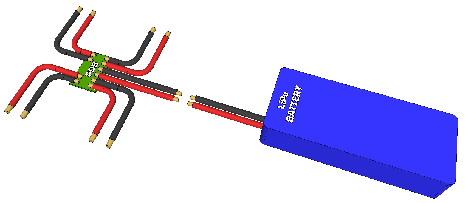 Power Distribution to Battery
Unplug the battery from the power distributor before you continue.
Motor -> ESC -> Power Distribution
The power distribution board (PDB) / cable is used primarily to split the main battery to each of the ESCs. The voltage is supplied "as is" to the ESCs, so there is no need to step up (increase) or step down (decrease) the voltage. If your multirotor uses four motors, you should have four ESCs and therefore your power distribution PCB / cable should at least split the main battery to four connections. If your PDB has six connections and you have a quadcopter, you don't need to have the last two connected. If you are building a hexacopter, your PDB should split the main battery into at least six connections. An ESC includes the following wires:- One 3-pin, 0.1" spaced R/C connector where the black pin is normally GND, the red pin provides 5V OUT (via BEC*) and the yellow / white connector is signal IN
- 3x separate wires to connect to the three wires on a brushless DC motor (normally supplied with female bullet connectors which are either soldered or included in the package)
- Two battery input connectors to plug into the PDB (some include male bullet connectors soldered, others are included in the package, and others are not included at all)
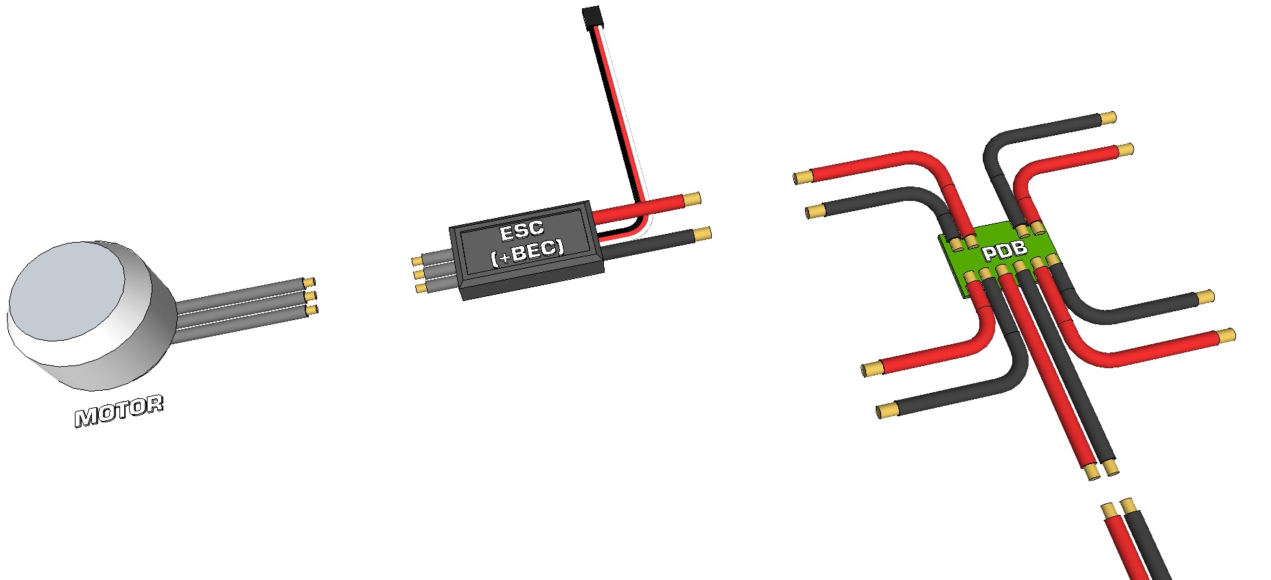 Motor to ESC (with BEC) to Power Distribution
If the PDB uses connectors which are not the same as those used on the ESC or the battery, then you will either need to purchase adapters, or purchase new connectors and replace those on either the ESC or the PDB. You can see the advantage of choosing a PDB which has the same connectors as your battery and ESCs. Normally the connector on a high current R/C LiPo battery is a red DEANS connector, yellow XT60 or blue EC3 connector. The battery’s white JST charging connector is not connected to the PDB. If you want to power additional low current electronics (LED lighting system, gimbal etc) but your power distribution board does not have any spare connections, you can consider using the battery’s charging cable. The white charging connector normally has one pin for GND, and one pin for each LiPo cell used to make up the battery pack. Despite really being designed for charging only, it does provide 3.7V output from each pin and can be used to power low current electronics such as a gimbal system or LEDs.
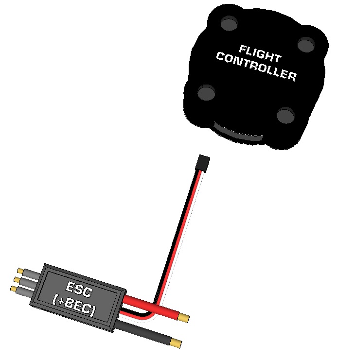
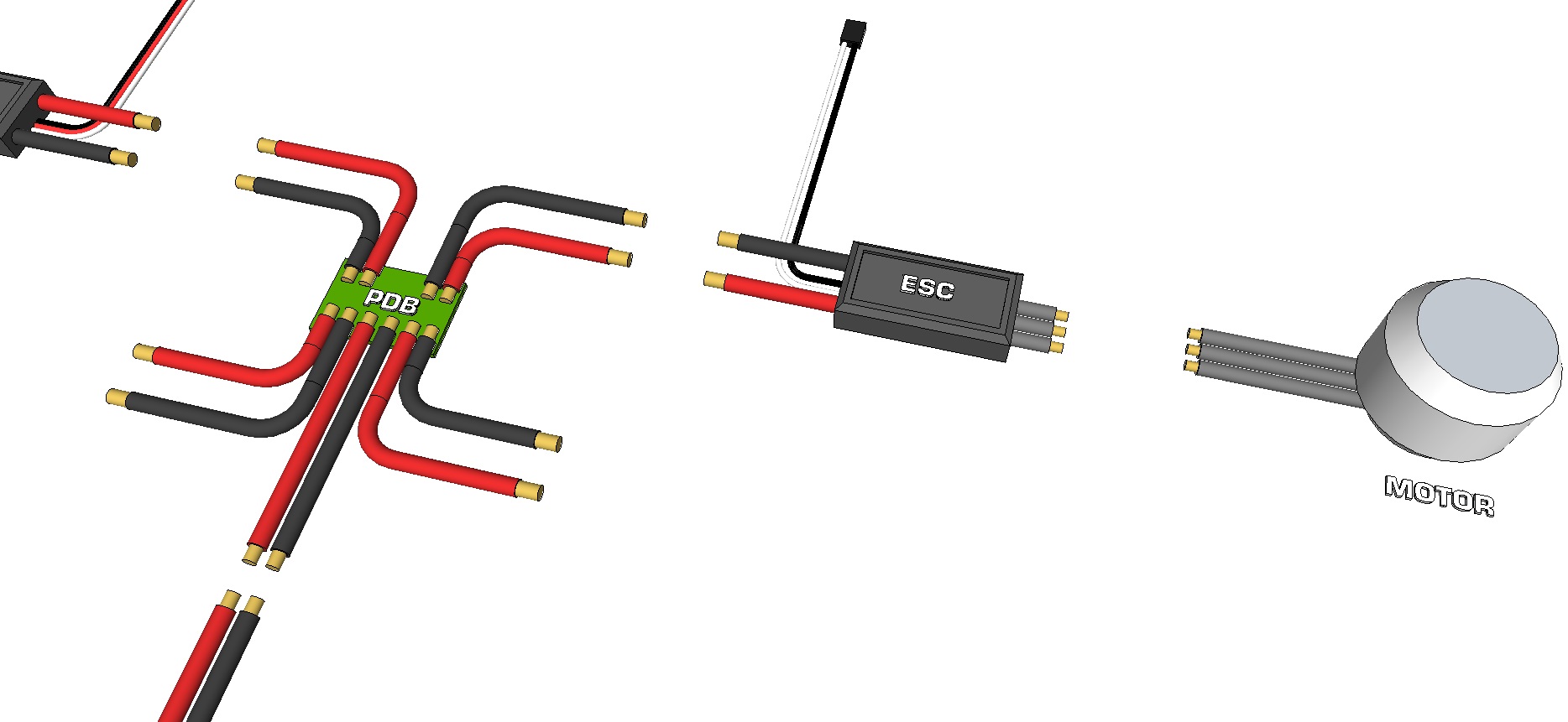 Motor to ESC (no BEC) to Power Distribution
- Remove the red wire from all but one of the ESCs' 3-pin R/C connector. We suggest removing the pin from the connector in such a way that you can reconnect it at a later time if needed. Wrap the loose pin in electric tape or heat shrink so it does not come into contact with any other electronics. The one with the red wire still connected will be powering your flight controller.
- Connect each of your ESC's two input connectors to the PDB, ensuring red goes to positive (+) and black goes to negative (-).
- If your PDB has R/C connectors, it is up to you if you want to connect the R/C pins from each ESC to this board, or connect them to the flight controller directly.
- Connect each of the motor's three bullet connectors to the ESCs' three bullet connectors. For the moment, it does not matter which of the three motor pins connect to which of the three pins on the ESC (if will affect the direction of rotation which will be corrected as needed later on).
 Only one ESC has the BEC connected
ESCs -> Flight Controller
At this time you can connect the ESCs' R/C input to the flight controller. The flight controller you chose should have a diagram showing which motors on your multirotor connect to which pins on the flight controller. The same diagram should also show the direction of rotation of each motor, but again for now, you do not need to consider the direction.- Look up the connection diagram between the motors / ESC and the flight controller in the flight controller manual
- Plug the R/C connectors of each ESC to the corresponding pins on the flight controller, ensuring the the ground wire (normally black) connects to the ground pin on the flight controller, and the signal pin (white or yellow) connects to the signal pin on the flight controller.
- Only one of the RC connectors will still have the red (power) pin connected; it does not matter which it is.
 ESC to Flight Controller
Communication
Receiver -> Flight Controller
In this lesson we must make the assumption that you have chosen to use a wireless RC radio controller as the input device. If you are looking to use WiFi, Bluetooth or other input method, please read through the flight controller's manual and look for serial input; that section will describe how / where to connect a serial input device to the flight controller. You will likely need to locate and connect the transmitting (Tx), receiving (Rx), voltage (5V) and GND pins from the wireless device to the transmitter, ensuring Rx from one goes to Tx on the other, and vice-versa.Your RC transmitter should have come with the appropriate RC receiver. The receiver should have been bound to the transmitter, so you can remove the binding jumper from the receiver (if one is included). The package may have also included a AA battery holder which is intended to power the receiver, but we will not make use of this since the BEC will be powering both the receiver and the flight controller. To know which channels of the RC receiver plug into which pins on the flight controller, you need to look at both the flight controller and the RC system’s user guide. The flight controller’s manual will specify the locations of the following pins which are to be matched and connected to the receiver:
- Throttle
- Pitch
- Yaw
- Roll
- Auxiliary (Aux) 1, 2, 3 etc.
 Flight Controller Receiver
You can now make the following connections:
- Read the flight controller's manual to see which R/C input pin is associated with which of the functions above
- Read the RC transmitter's manual to see which channel is associated with each of the functions
- Some RC transmitters can be reprogrammed to change the function of each pin, so if you decide to change which input (joystick or switch) does what, then be sure to know which channel on the receiver will correspond to which function. Throttle, pitch, yaw and roll should always be associated with the two joysticks, not with switches or knobs.
- Connect the throttle channel on the receiver to the throttle input on the flight controller
- Connect the pitch channel on the receiver to the pitch input on the flight controller
- Connect the yaw channel on the receiver to the yaw input on the flight controller
- Connect GND on the flight controller (normally the third row of pins) to GND on the receiver (normally the third row of pins)
- If an auxiliary input is used, connect Aux 1 on the receiver to Aux 1 on the flight controller and so on.
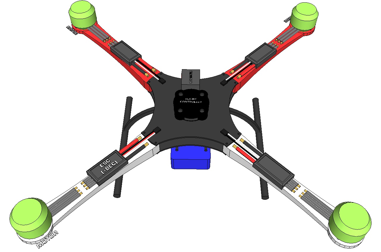
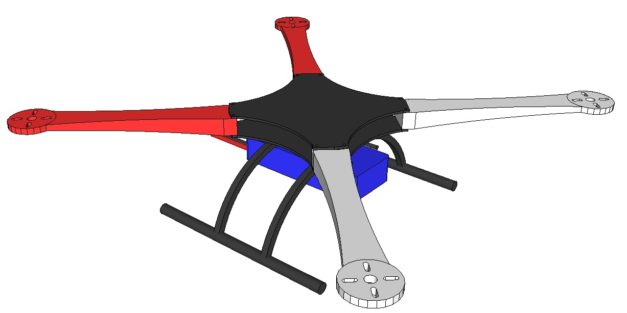
Frame Assembly
If you are building your own frame, you can assemble it at this step. If you purchased a frame kit, follow the assembly guide. Note that you may need to disassemble certain areas to make wiring easier or to clean it up.The objective is to ensure nothing is loose, all wires are properly secured and nothing can fall out of the frame or get tangled. Multirotor Frame
Mounting
Battery Placement
The battery used to power a drone is often the heaviest item on a UAV, and can often account for 1/4 to 1/2 the total weight of the vehicle. As such, its mounting location is quite important. The ideal location of the main battery would be at the center of the copter so as to ensure all motors have to support roughly the same load. If the battery is placed more towards the rear of the copter, the rear motors will need to provide more thrust than the motors at the front, and as such, the maximum total thrust will be limited (when the rear motors are at full thrust, the motors at the front will not be). Given that the normal approach to multirotor design is to have the copter symmetric about the center axis (or at least one axis), the battery should also be placed along this center line, and not offset to one side or the other. Next you will want to determine at which height to place the battery. There are several places where a battery can be mounted:- Below the frame (copter will be bottom heavy, more stable and less acrobatic).
- Just below the motors (normally inside the frame); arguably one of the better locations
- At the same height as the motors or propellers (for example mounted to the top of the frame)
- Above the propellers (UAV will be top heavy and more inclined to flip)
 Battery Placement / Mounting
Battery Mounting
There are a variety of commonly accepted ways to secure a battery to a frame and include:- Velcro straps
- Adhesive Velcro strips (one side secured to the battery and the other to the frame)
- Enclosed within the frame
Battery Charging
It is very likely that you will have chosen a Lithium Polymer (LiPo) or other Lithium-based rechargeable battery pack. Most LiPo batteries above 3.7V have a separate multi-pin connector for charging the battery, while the main connector can be identified by having a two-pin connector with larger wires, capable of handling high discharge current. The charging connector normally has one pin for each of the cells used in the battery, as well as a common ground pin. Because of the dangers inherent to LiPo batteries (hydrogen and electricity), it is common practice to remove the battery completely from the drone when it is not in use and place it inside a LiPo Safe bag. This same bag is used when charging the battery (connect the battery to the charger, place the battery in the bag (leaving the charger outside of the bag) and seal the bag (they normally include a flap with Velcro).Flight Controller Placement & Mounting
The flight controller should ideally be located at the center of the drone at the same height as the motors. If this is not possible, then the controller can be put slightly above or below. You should not mount the flight controller more towards the left or right side, and avoid mounting it more forwards or backwards. If you purchased a UAV frame, they often have mounting holes for the flight controller which are at the optimal location. the flight controller can be secured using any of the following main methods:- Screws / nuts / standoffs (basic)
- Double-sided adhesive tape (ensure it's strong enough)
- Double-sided adhesive foam (for a damping effect)
- Rubber grommets (for significant damping)
 Flight Controller to Frame
ESC Placement & Mounting
The ESCs are connected between the motors, the power distribution board / cable and the flight controller. The standard wire length included with the ESC, combined with the motor's cables often mean you don't need to add any cable extensions. The ESCs need to provide high current and as such are usually quite hot when in use. The ideal location would be directly below the propeller wash on the support arm; this forces air over the ESC which helps to cool it off. The ESC can be secured to a support am using zip ties (one on either side of the ESC), tape or almost any other method which will not impede heat dissipation. The ESCs should not be mounted in a location which will restrict heat dissipation (like an enclosed metal box) and should be located a distance away from sensitive electronics like the flight controller or receiver. ESC & Motor Mounting
RC Receiver & Antenna
The RC receiver itself can be located almost anywhere on the multirotor, except it is best not to place it too close to wires which are carrying high current (so away from the battery and ESCs). The receivers included with RC systems tend not to have any specific mounting method, so quality double-sided adhesive is the best option. The antenna which is attached to the receiver is usually a flexible wire. This wire should be located such that a wireless signal is not impeded, while keeping it as straight as possible. Taping the receiver's antenna along a support arm (on a side opposite to the ESC's wires) or along landing gear are the best options. In lesson 6 we will talk more about range testing, which should be done to know the maximum distance at which the receiver picks up a signal from the transmitter. Range testing may require that you experiment with different locations for the receiver and antenna. Receiver Antenna Placement
GPS Antenna Placement & Mounting
Unlike the receiver's wire antenna, the GPS receiver's antenna tends to be either a duck antenna (rigid plastic pole either fixed, 90 degrees or hinged) or rectangular and relatively flat. Some GPS units have an integrated antenna (i.e. the antenna is part of the printed circuit board). In either case, the GPS antenna should be mounted at the top of the UAV so satellite signals are not blocked. Mounting a rectangular antenna is normally done using double-sided tape, and mounting a duck antenna usually involves drilling a mounting hole. If the duck antenna connects directly to the flight controller, no additional mounting is needed.At this point you should have your complete multirotor built, assembled and wired, except for the propellers. Lesson 6 involves setting up and testing your transmitter, the flight controller’s software, a pre-flight check and your first flight.
This is a companion discussion topic for the original entry at https://community.robotshop.com/tutorials/show/how-to-make-a-drone-uav-lesson-5-assembly