

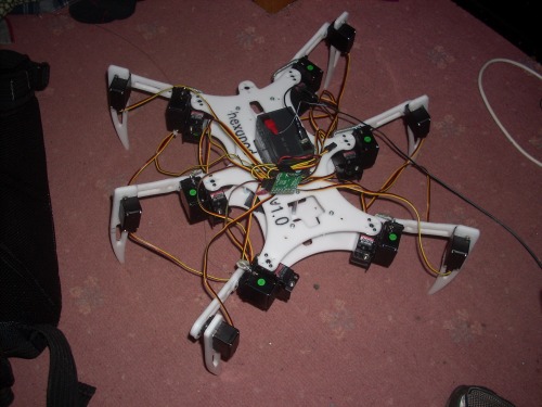
finally have the PCB's made up, and on the 30th november it took its first steps :)
If you have any questions about this robot, leave a comment, or you can email me at [email protected]
update:
Most recent work with this robot has been code development. Text to speech module has also been added. The new code allows the robot to walk in a direction (sideways at the same time as forwards) instead of only being able to walk in a streight line and turn on the spot. Also I have done a couple of small bits in the code to make the robot look more realistic, when standing, the body will tilt and rise up and down randomly, and will always rise and fall slightly as if breathing. The rate of "breathing" is dependant on how long ago it was moved and how fast/for how long it was moved.
Tilt control has been added, the controller has an accelerometer that is used to tilt the robot.
Servos:
- hip servos (12x HiTec HS-475HB) (https://secure.servoshop.co.uk/ )
- knee servos (6x HiTec HS-422) (https://secure.servoshop.co.uk/ )
- Sensor servos (3x EMAX ES08A) (https://secure.servoshop.co.uk/ )
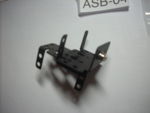
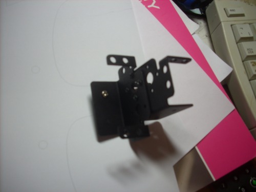
- ASB-04 brackets for mounting the hip servos (http://www.active-robots.com)
- BB-03 bearings for mounting hip servos (http://www.active-robots.com)
I purchased all the servos from servoshop ( https://secure.servoshop.co.uk/ ) (i would highly recommend them, site looks a bit dodgy in places, but service is excellent, site is secure, products are as promised, and prices are very good)
The brackets are bolted together, and the bearing is bolted to the bottom of one (so it will be inline with the servo horn so as to make a strong pivot point). The servos are now bolted to the brackets using M3 bolts (this setup is the same as used in the lynxmotion pheonix).
Building material/process:
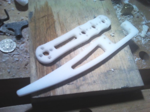
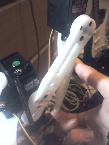
- 5mm Acetal (used for the leg pieces) (http://www.directplasticsonline.co.uk)
- 3mm Acetal (used for the man chassis) (http://www.directplasticsonline.co.uk)
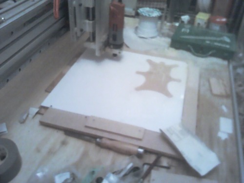
The parts were designed using QCAD (easy-to-use open source software)
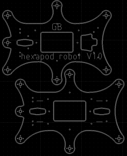
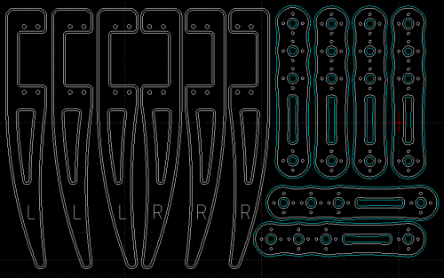
The parts were machined from acetal using a friends CNC milling machine, they needed a lot of finishing after being cut, but looked pretty good afterwards. The toolpaths were created using Vetric cut2D (trial edition). This is a free download, (limited use) but works flawlessly and is easy to use (runs perfectly under WINE for linux users).
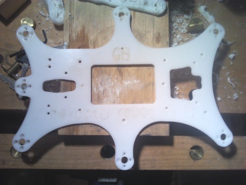
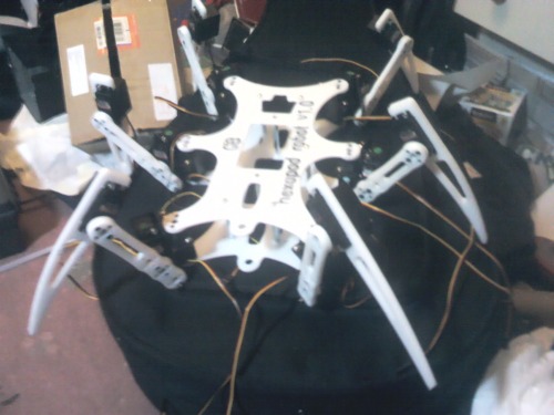
After all the parts had been machined and finished of they are bolted to the servos, and the main chassis is ready. All the parts were assembled by attaching them to the servo horns with standard servohorn screws.
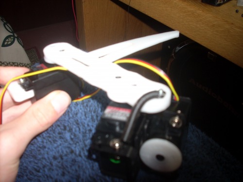
When testing with this model i found that the servo torque rating was a bit on the edge, so i decided to add some load-balencing springs (one set on each leg) that will pull the leg downwards reducing the need for high servo torque. This was done by mounting a spring between the lower end of the leg, and the M3 bolt holding the leg servo to the bracket.
The single springs turned out to be to powerfull, so i ended up adding two weaker springs in parallel to each leg. At the moment the springs to rub over the leg part as it moves, so i am going to make a thin aluminium cover to cover the edge of the leg piece to prevent wear of the leg by the spring.
Adding springs to each leg gives enough lift force to hold the whole robot + lead acid battery without powering the servos! roughly 24N of force can be provided when all 6 legs are in contact with the ground, meaning that whilst the hexapod is walking, (3 legs in contact with ground at a time) it will be able to carry 3Kg (its own weight + 800g).
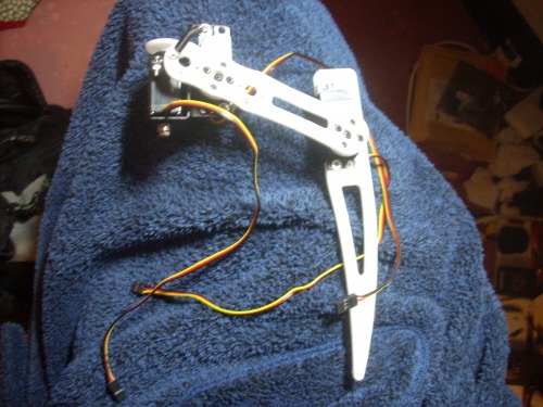
To allow this robot to be autonomous, it will need some sort of vision, I have added 2 infra-red range sensors (one on the front, and the other pointing downwards). both will be mounted to micro-servos, allowing the robot to look around. The sensor pointing downwards will let the robot know how far from the ground it is, and whether it needs to stand higher.
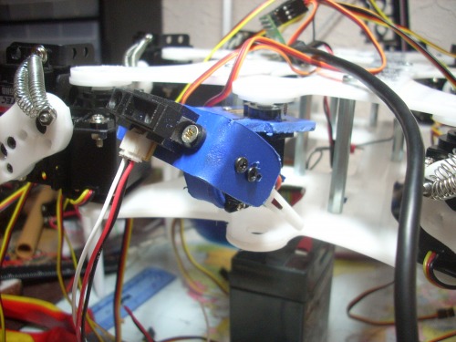
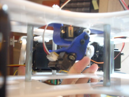
The picture on the left is the sensor mounted on the front of the robot, (this is a 2DOF mechanism using 2 micro servos), and the picture on the right is the ground level sensor (1 DOF mechanism using 1 micro servo). The blue brackets are made out of some engineering plastic i had lying around, and were bent by heating with a match and using a 90 degree edge. I am planning to add a small camera to the front bracket as well as a PIR detector. The camera I have selected (http://www.active-robots.com/sensors/camera-vision/cmos-camera-1300x1040.html) will be able to be connected to the I2C output on my PCB
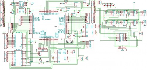
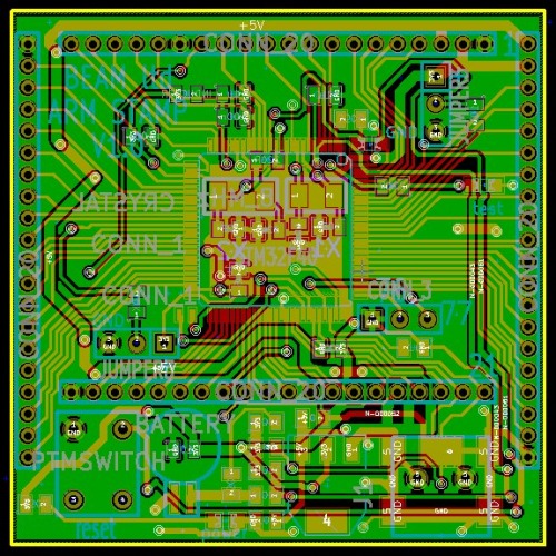
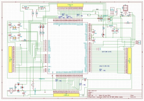
Electronics design and build
will include:
- accelorometer,
- gyroscope,
- radio module
- control for 4 reversable motors
- control for up to 24 servos (8 with current sensors)
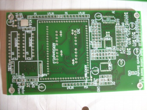
I am going to use an SPI interface to connect the accelerometer, gyroscope and radio module to the main processor, and an I2C interface to connct the PWM chips (used for servo control and motor speed control). I am using two L293D motor control drivers, and feeding a pwm signal into the "motor enable" pins to control the speed. This allows for the speed control of 4 reversable motors. The current measureing on the servo channels is done to allow the processor to know when the legs are in contact with the ground. I am using a multiplexor to connect the outputs from the current sensors, this allows more than one device to be connected to an analogue input on the processor (it can connect all 8 devices to one analogue channel on the processor meaning I can use the other analogue input for other devices).
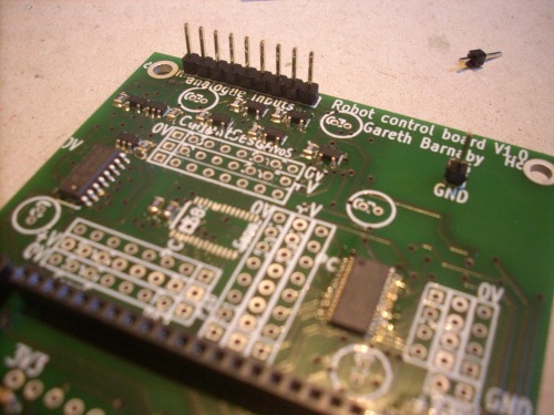
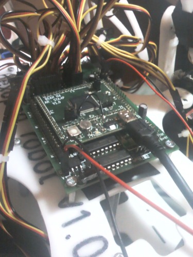
The PCB also allows for the use of extra analogue and digital inputs and outputs for general purpose use such as cameras, distance sensors, bumpers or LED outputs etc. Two of these boards will be made, One for being mounted to the actual robot, and the other to be used to control the robot when its not running autonomously.
Latest PCB mods:
7/11/2012
- Added I2C interface .1 inch SIL output pins for control of external devices
- Added motor jumper to allow all 4 motors to be powed from the same power supply
- Added capacitors across the Accelorometer, Gyroscope, and radio module power supplies
- Added 3mm mounting holes (one in each corner)
10/11/2012
- Added 100uF capacitors across servo power supply to reduce power spikes at high currents
- Added Multiplexor
- Changed 5V regulator from T0220 to DPAK-3 case style
- Added current sensors to 8 servo channels
- Added current sensing to 8 of the servo channels.
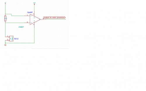
The current sensors are based on Op-amps. This works by putting a resistor in series with the servo power, and using an OpAMP to meaure the voltage drop across the resistor. Each servo takes around 1 amp when under severe load, and the main processor runs on 3.3Volts. The OpAMP i will be using has a gain of around 500, meaning the resistor i need to put in series with the power source needs to be around 0.05 ohms. ((3.3/500)/1) (voltage/gain)/current
12/11/2012
-
spread out main 100uF capacitors across servo power supply to increase their affect,
-
added capacitor across main power input (6V in)
-
added ground pin to allow for easy signal testing using an oscilliscope
-
added 0 ohm resistors in series with current sensor outputs, allowing the analogue inputs to the multiplexor to be used for other external devices instead of the current sensors.
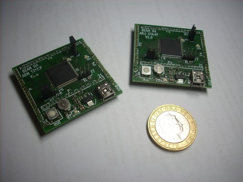
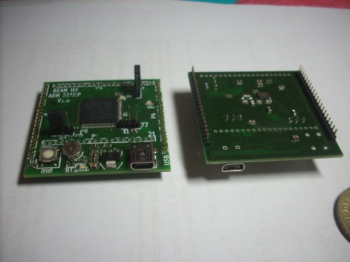
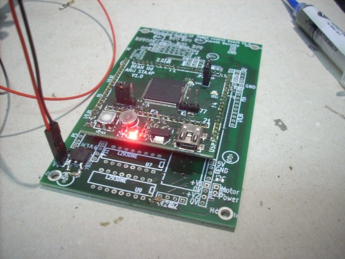
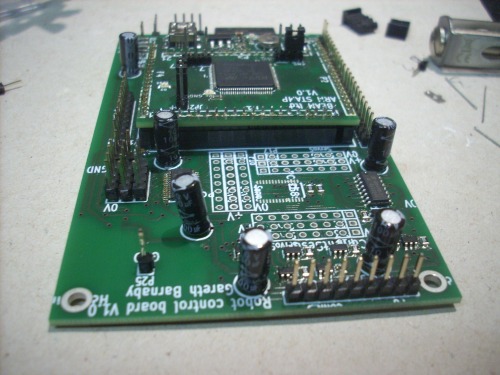
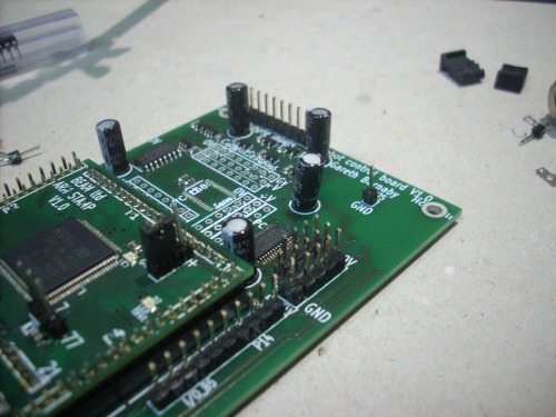
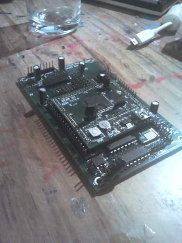
my main control board has been designed to be controlled by an ARM based breakout board which I also designed using KiCAD. This breakout board had all the nesacarry hardware for the processer to run (power supply, USB programming port oscillaters etc). The breakout board has 4 rows of 20 2mm SIL plugs, and will plug onto my Board, allowing a single breakout board to be easily used in any project.
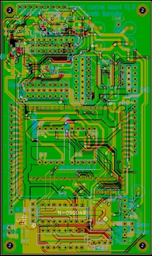
Update (20/11/12):
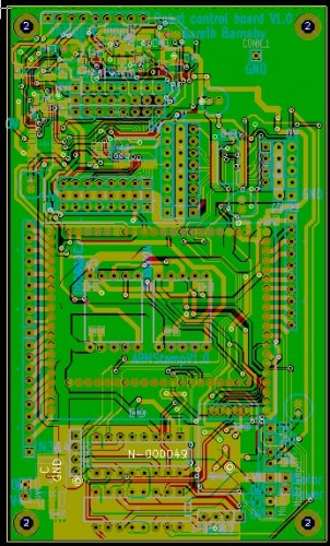
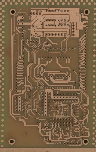
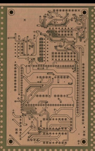
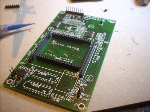
I have got back some of the photos from the main board manufacturing, (The company that is building them do high quality custom boards very cheaply, and i would recommend them if you want something similar done --> http://www.pcb-pool.com/ )
Text to speech:
I have added an I2C text to speech module (EMIC 2) to the electronics.
It works very well, and is easy to control with the I2C (just send it a string and it will speak the string).
Software:
The robot is programmed using C++.
V1.4 code is attached.
Power supply info:
When testing the robot when walking normally in a streight line witht he first walkign gait, i found that the servos were only taking 2.5 amps between all of them. This meant it was fine to use rechargeable AA's to power the servos. (i Used them due to high power/weight ratio, and general convinience). The robot can hold up to 10AA batteries at a time (2 parallel sets of 5 cells in series). I use 2800MaH batteries meaning that 10 batteries can power the robot for approx 2 hours. Alternatively, the robot can be powered by 5AA's at a time, but the batteries will only last half as long.
The electronics are powered by a 800MaH 9.6V NiCD pack (from an old radio controlled car). With all the extra bits the circuitry takes around 100MaH (this includes servo drivers, radio module, speech module etc). This battery should last around 8 hours, but in reality only lasts about 3 as it has been heavily used.
programming platform
- Actuators / output devices: Servos
- Control method: will be both autonomous and radio controlled
- CPU: 2 x ARM processors (STM32F405)
- Operating system: no OS at this point in time..., will be programmed in C++
- Power source: 6V lead acid (hoping to upgrade to NiCAD pack / AA's)
- Programming language: will be programmed in C
- Sensors / input devices: Current sensors, strain gauges
- Target environment: Indoor/Outdoor
This is a companion discussion topic for the original entry at https://community.robotshop.com/robots/show/homebuilt-hexapod
 I dont have any experience with straight nylon, but the acetal is extremely sturdy stuff, the 5mm legs are at around 1 cm width at their thinnest point, and they only bend a mm or two when you push on it with your thumb, very suitable for use as legs in my opinion (also lightweight and relatively easy to machine