

I want to make a precision laser scanner for topography applications.
I would like to know how to determine the angle of each measurement very precisely so as to obtain the X, Y, Z coordinates.
What sensor and hardware you need.??
This problem has two parts:
- Which laser scanner (accuracy, resolution, maximum distance, etc.)
- How to know the angle with reference to the ground.
For the first issue, you could browse our LIDAR category here. A good option may be the RB-Mrp-01. It has a range of 150 m, an accuracy of 5 cm (~0.03% !) and a protection of IP67 (ip codes).
We also have other, slightly less expensive options such as the RB-Plx-317 (100 m range, accuracy ~10 cm), (50 m range, accuracy ~10 cm) and RB-Pli-06 (40 m range, accuracy ~1 cm).
For the second issue, the easiest way to know orientation is to compare the positioning of your sensor to gravity (force). This can be done easily using an accelerometer. Since you want high precision, the best would be to choose an accelerometer with very high precision. You can see accelerometer products here. A very good one is the RB-Phi-166.
Sincerely,
Hello scharette …
Thank you very much for your prompt response.
I have doubts that the number to refence better.
For the telemetry sensor I’m going to get it for Garmin Lidar lite v3 - RB-Pli-06. (For its precision, besides that I have a new one)
1.-For the accelerometer It draws my attention RB-Phi-166. But it is compatible with Arduino Mega 2560?? (I plan to use Arduino Mega 2560 for its superior power to the basic Arduino.)
2.-If it is compatible as the connection, since I have never used any module with USB interface
Deepening the project
I was reading all your advice in the post related to Lidar lite 3v where you stuck to a person that ideal to scan as if it were SLAM ideally would use a rotating mirror on the Lidar lite v3. (I think it would add a motor for the horizontal movement and thus cover the entire area.
I thought to use two engines one that rotate the lidar lite horizontally and another that rotate it vertically to cover the whole area.
3.- On the basis of the above and the comment of the other post, which believes that of better results (precision), which will be easier to perform.
Regards!
Hi,
A device such as the RB-Phi-166 is meant to be used by a USB host (such as a computer, laptop, or even a Raspberry Pi). The Arduino Mega 2560 may be able to use it with a USB host shield, but that requires special device drivers (which may or may not be easily found).
As for using the LIDAR-Lite with a mirror, it is a simple solution that does produce good results without needing a slip-ring or other complicated mounting.
If you move your sensor using two motors, you may want to place the accelerometer directly on the motor itself (maybe attached with double sided tape or similar). This would allow you to have its proper angle with reference to the ground (gravity).
Either method would be not too complicated to use, but the rotating mirror would make it harder to know the angle the sensor is pointing at since you would need to also know the position of the mirror. Therefore, a method using what would basically be a pan & tilt might be simpler to use.
Sincerely,
Good morning Sebastien …
Based on your observations, I will have to opt for another sensor, open some that you can recommend that is compatible with the Arduino Mega 2560 pins and high precision, there are several and I do not know which to select.
I have a MPU-6050, although it is low-end, do you think it will serve me for the prototype and then fit it for which you recommend me?
I want to get X, Y, Z for trigonometric functions and convert the polar coordinates to Cartesian coordinates …
Is there another way to get the cloud of points without using the accelerometer ???
The MPU-6050 (we have a breakout board for it here) should do fine for prototyping / proof-of-concept.
Just make sure to change its range of acceleration to ±2 G. Once your device is stable, you will get a good reading on the gravity (1 G).
As for conversions, there are many examples available online, such as this, this and this.
The main point of the accelerometer is to tell you exactly where ground is. From there, you will only need to know the difference between where your sensor is pointing and where the accelerometer is. If you mount the accelerometer on the sensor with an axis pointing where the sensor is, then this becomes very easy!
If you have another way of ensuring your device is leveled, then you can simply extrapolate the angles of the sensor from how it is mounted and rotated by your two-motor system, though this may be very imprecise.
To be honest, while this is not a very complicate project, it is certainly **not **trivial, either. You’ll most likely have to do quite a bit of reading to get everything integrated properly.
Sincerely,
Hello scharette …
I’m absent but I’m back…
I’m reliving this project…
make a scheme of the prototype that I would like you to see and give me your opinion.

Looking at this image, I have the following doubts.
1.- if we place an engine with an encoder instead of the MPU.
an engine with encoder of this type:
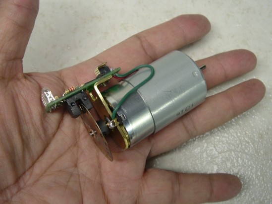
which of the two cases will give me more angular precision.??
2.-Where can I get this type of motor with encoder?
3.-Can you give me your view of my scheme?
regards
Welcome back (and to our new community site, too!!!)!
Better late than never, as they say! ![]()
As oppose to an accelerometer/IMU? Well, it really depends on the resolution of the IMU and the encoder. Also, it should be noted that the accelerometer part of the IMU is only good at telling you how what it is mounted to is placed related to gravity (if static or acceleration vector if moving).
If your IMU is not directly mounter on the sensor (or tied to it directly at a known angle), you’d still need some form of encoding or feedback to know how the sensor ('s direction or “sensing vector”) and IMU relate to each other.
In the sketch of your idea that you have above an encoder on a back shaft of an actuator (DC motor?) sounds like a good plan. That being said, there might be some simpler options since the load on that motor is known (and fixed) by design: use a stepper motor instead (in direct drive).
Since the load is known you can ensure the stepper motor always has enough torque (and therefore never slips/skips a step). Because of that you can use the amounts of steps as the encoder. Easily available (and low cost) hybrid stepper motors typically have resolution per steps of 0.9° or 1.8°. Of course, if you take a slightly beefier stepper motor than you can use half, quarter or even 1/8 steps and increase that resolution immensely. As a point of reference, mid-range rotating LIDARs (~500-1500 USD) typically have angular resolutions of ~0.2°-0.3°, so you’d be in a decent range of resolution.
You can get some right here on RobotShop! Here is an example of a gear motor with encoder: RB-Dfr-439; more options here. According to documentation, this motor’s encoder has 663 pulses/rotation and therefore an angular resolution of ~0.54°. Please note that most of these encoder types are all incremental (not absolute) and therefore you still need some other sensor or method of providing a “zero” to start counting from. A limit switch of some kind or a hall effect sensor could work well as a zero.
We also have plenty of high quality encoders you can couple to a DC motor back shaft of your choice to get high resolution readings. You can see our encoder & disk catalog here. Here are some examples that provide good resolution:
RB-Spa-1042, 1024 pules/rotation (~0.35° angular resolution)
RB-Smh-01, 5000 p/r (~0.072° ang. res.). This one even has a waterproof version, too, but does not come with the coupling to attach (we also offer those here).
Since you will be doing 3D scans and will be using a mid-range LIDAR (~up to 40 m), the better the angular resolution the better your scan (as long as you can scan it fast enough).
Of course, as you can see from the links above, good quality encoders are expensive so using the stepper makes even more sense if cost is an issue (and also reduced complexity of design!).
It seems like it would work OK. It really depends more on the components and integration done with this design. If this is your first project of this type expect to most definitely face a few hardships and implementation issues. But that is true of all new projects, right? ![]()
Good luck with the revival of your project!
Sincerely,
Hello Scharette…
thank you very much for your prompt response.
at the moment I will use the motor steps because of the cost.
1.- What do I need to check to choose a motor with good precision steps? (her CARACTERISTICS)
2.- Stepper motor has good rotation speed for faster scans?
One of the most important characteristics when it comes to motors is torque. If your motor cannot do the work required then it will simply not work.
As a good rule of thumb, I recommend trying to get a motor that can produce enough maximum torque so that your use case falls within 20-25% of that maximum. This will allow the motor to not overheat to much and work for longer periods of time.
The stepper motor’s main advantage is knowing your position implicitly from your motion. This assumes it never slips/misses a step (see point above concerning torque).
It should also be noted that at higher speeds (more steps/s) the torque produced by steppers motors drops sharply (unlike with DC motors, where more voltage => more speed/torque produced).
Similarly, if you use fractional steps (typically called microstepping) to increase accuracy you will also greatly reduce torque.
A good solution for this is to use a beefier stepper motor that way you can both move really fast but also use microsteps for good resolution.
Concerning scanning in general you’d probably want to have the best resolution possible when scanning (especially at long distances). Since you can easily find hybrid stepper motors with step sizes of 1.8° and 0.9°, you can then increase your scanning resolution by simply using microsteps. As mentioned above if microsteps are used you will need to get a stronger stepper motor.
I recommend checking out this article about microstepping.
I hope this info helps! ![]()
Sincerely,