John_NY_GFX_board1.png (14203Bytes)
John_NY_GFX_schematic1.png (10602Bytes)
John_NY_GFX_board2.png (8625Bytes)
John_NY_GFX_schematic2.png (5981Bytes)
DSCN1523.JPG (17196Bytes)
John_NY_boardfabtop.JPG (26694Bytes)
John_NY_boardfabbot.JPG (40932Bytes)
clone_cnc_pps1_board_med.JPG (378909Bytes)
clone_cnc_pps1_board_sm.JPG (70262Bytes)
clone_cnc_pps1_setup_med.JPG (423071Bytes)
clone_cnc_pps1_setup_sm.JPG (77472Bytes)
sparkfun.png (29238Bytes)
clone_cnc_pcb_gcode_generation.png (13078Bytes)
clone_cnc_pcb_gcode_machine.png (12118Bytes)
clone_cnc_pcb_gcode_board.PNG (14531Bytes)
clone_cnc_pcb_gcode_options.PNG (11664Bytes)
pedal_supply_A_01.JPG (181208Bytes)
pedal_supply_A_02.JPG (184238Bytes)
pedal_supply_A_03.JPG (158191Bytes)
pedal_supply_complete.JPG (3159221Bytes)
Pedal_supply_punkrock_01_small.JPG (42466Bytes)
Pedal_supply_punkrock_02_small.JPG (44047Bytes)
Pedal_supply_punkrock_01.JPG (681820Bytes)
Pedal_supply_punkrock_02.JPG (180575Bytes)
pedal_insides_01.JPG (88383Bytes)
PS-01.jpg (446882Bytes)
PS-02.jpg (647719Bytes)
PS-04.jpg (775084Bytes)
PS-03.jpg (691409Bytes)
guitar_effects.png (3747Bytes)
Effects_Pedal_Trimpot_Evaluation.xls (18432Bytes)
Effects_Pedal_200mA.png (6376Bytes)
Pedal_Board_01a.jpg (56696Bytes)
Pedal_Board_02a.jpg (56317Bytes)
Pedal_Board_03a.jpg (50962Bytes)
Pedal_Board_04a.jpg (44713Bytes)
https://www.robotshop.com/letsmakerobots/files/PS-01.jpg
https://www.robotshop.com/letsmakerobots/files/PS-02.jpg
https://www.robotshop.com/letsmakerobots/files/PS-03.jpg
https://www.robotshop.com/letsmakerobots/files/PS-04.jpg
https://www.robotshop.com/letsmakerobots/files/Pedal_Board_01a.jpg
https://www.robotshop.com/letsmakerobots/files/Pedal_Board_02a.jpg
https://www.robotshop.com/letsmakerobots/files/Pedal_Board_03a.jpg
https://www.robotshop.com/letsmakerobots/files/Pedal_Board_04a.jpg
Abstract: I built a power supply (R.G. Keen's Guitar Effects Pedal Power Supply) as a gift; it is one of my first projects using the Valkyrie-clone CNC machine for PCB fabrication. The Power Supply is a bow power supply, and the source is at http://www.geofex.com/Article_Folders/Spyder/Spyder.htm
One board has 6x basic regulators, another has 2x "Deluxe Regulators". The resistors for "deluxe" are specified 240, 1.1k, a 500ohm trimpot and a 100ohm trimpot. The 100 ohm trimpot must be capable of 0.5 Watt dissipation.
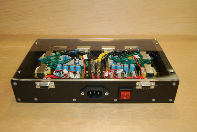
The Xicon transformers (Mouser part #41PG006) are mounted seperately: the leads from the secondary coils go to the AC jumpers. Each 4 DC outputs are connected to a DB-9 connector; the DB-9 connector attaches to four 2.1mmx5.5mm DC barrel jacks, negative pin, which connects to most effects pedals.
https://www.youtube.com/watch?v=nHmdzAsNSSE


